Drilling tool

A technology for drilling tools and tools, applied in drilling accessories, manufacturing tools, drilling/drilling equipment, etc., can solve the problems of chip winding without mentioning, and achieve excellent practicability, stable drilling processing, and prevent The effect of winding of chips

Active Publication Date: 2013-11-13
UNION TOOL
View PDF8 Cites 3 Cited by
  • Summary
  • Abstract
  • Description
  • Claims
  • Application Information

AI Technical Summary

Problems solved by technology

[0013] In addition, although, for example, Patent Document 4 discloses a technique in which, on a PCB drill having two cutting edges and two chip flutes, the chip flutes are merged at a position retreated by a predetermined amount from the tip, A groove is formed behind the meeting point, thereby improving the rigidity of the drill, but Patent Document 4 does not mention the winding of chips, and the above-mentioned requirements cannot be met.

Method used


Image

  • Drilling tool
  • Drilling tool
  • Drilling tool

Examples


Embodiment

[0053] based on Figure 4 ~ Figure 10 Specific examples of the present invention will be described.

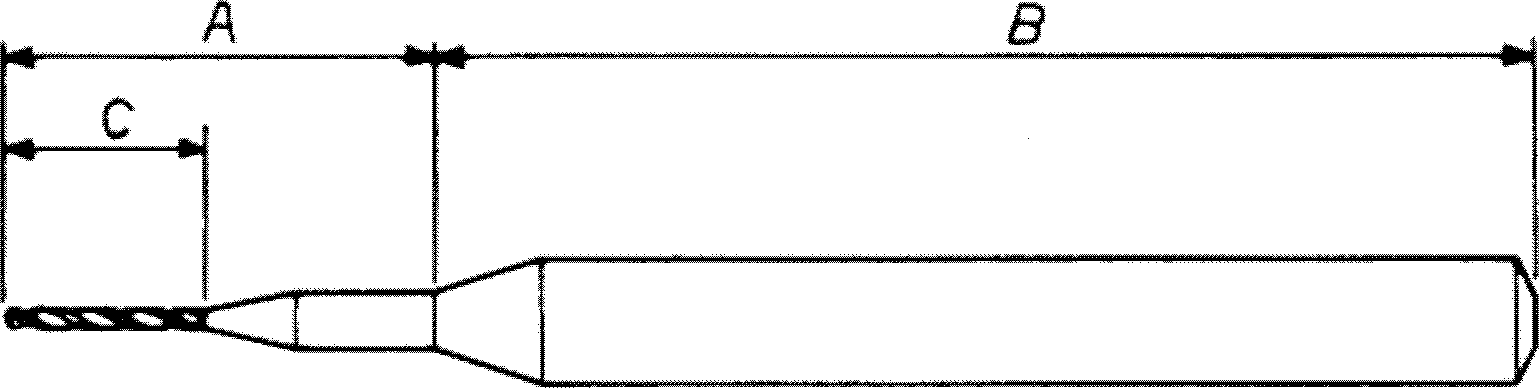
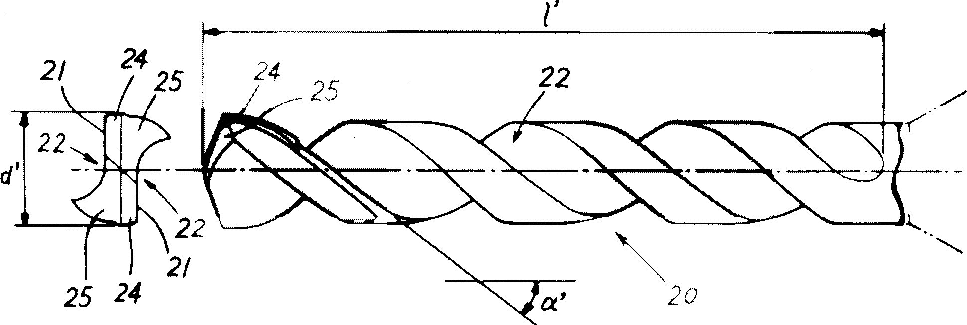
[0054] This embodiment is a drilling tool as follows: one or more cutting edges are provided at the end of the tool main body 1, and a plurality of helical cutting edges are provided on the outer periphery of the tool main body 1 from the end of the tool toward the base end side. Chip removal flutes, the plurality of chip removal flutes at least include one main flute 2a and one auxiliary flute 2b, and one or more auxiliary flutes 2b are arranged in the middle of the main flute 2a and the main flute 2a In addition, the drilling tool is provided with a step difference 7 at the confluence part 6 where the main groove 2a and the secondary groove 2b meet.

[0055] Specifically, the present embodiment is a drill bit as follows: the tool diameter is 0.075mm, and one main groove 2a and one auxiliary groove 2b are respectively provided, and the groove length l of the main groove 2a i...


PUM


Abstract

The invention provides a drilling tool, which is capable of preventing chip winding and capable of stably drilling holes by using a small-diameter drill bit with a diameter smaller than 0.7 mm, in particular smaller than 0.4 mm, and achieves long breakage-resistant lifetime and excellent practicability. The tail end of a tool body (1) is equipped with one or more cutting blades. Multiple helical chip-evacuating grooves are formed in the outer circumference of the tool body (1) from the tail end of the tool body to the base end, wherein the multiple chip-evacuating grooves at least comprise one main groove (2a) and one auxiliary groove (2b). The one or more auxiliary grooves (2b) are joined with the main groove (2a) at the halfway portion of the main grove (2a). In addition, the join portion (6) where the main groove (2a) and the auxiliary groove (2b) are joined has class difference (7).

Description

technical field [0001] The invention relates to a drilling tool. Background technique [0002] Used in the drilling of printed circuit boards (PCB) such as figure 1 A drill as shown is composed of a drill body A having a cutting edge C and a shank B. As shown in FIG. Depending on the application, the size of the drill varies, but generally speaking, drills with a diameter of 0.7 mm or less are used. [0003] Specifically, on the blade C, such as figure 2 As shown, a helical chip flute 22 is formed on the outer periphery of the main body 20 from the drill tip to the base end side. The cutting edge 21 is formed at the intersecting ridgeline portion (for example, refer to Patent Documents 1 and 2). In addition, in the figure, reference numeral 25 is a second relief surface, and the second relief surface 25 is continuously provided on the rear side of the first relief surface 24 in the tool rotation direction, d' is a tool diameter, and l' is a flute The groove length, α' ...

Claims


Application Information

Patent Timeline
Patent Type & Authority Patents(China)
IPC IPC(8): B23B51/00
CPCB23B2251/24B23B2251/40B26F1/16B26F2210/08H05K3/0047
Inventor 星幸义安田俊夫
Owner UNION TOOL
Why Eureka
Try Eureka