

Pressure pad device of mechanical press
A technology of mechanical presses and pressure pads, applied in the directions of presses, manufacturing tools, etc., can solve the problems of high production cost, high pit cost, and economic burden of enterprises, and achieves saving manufacturing cost, reducing gas source consumption, The effect of reducing the cost of use
- Summary
- Abstract
- Description
- Claims
- Application Information
AI Technical Summary
Problems solved by technology
Method used
Image

Examples
Embodiment Construction
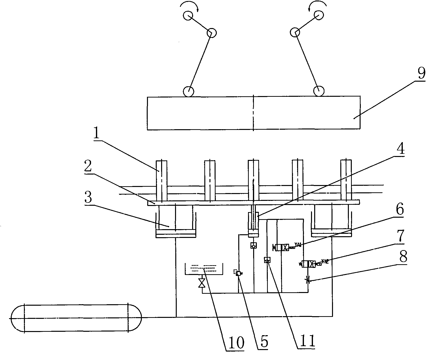
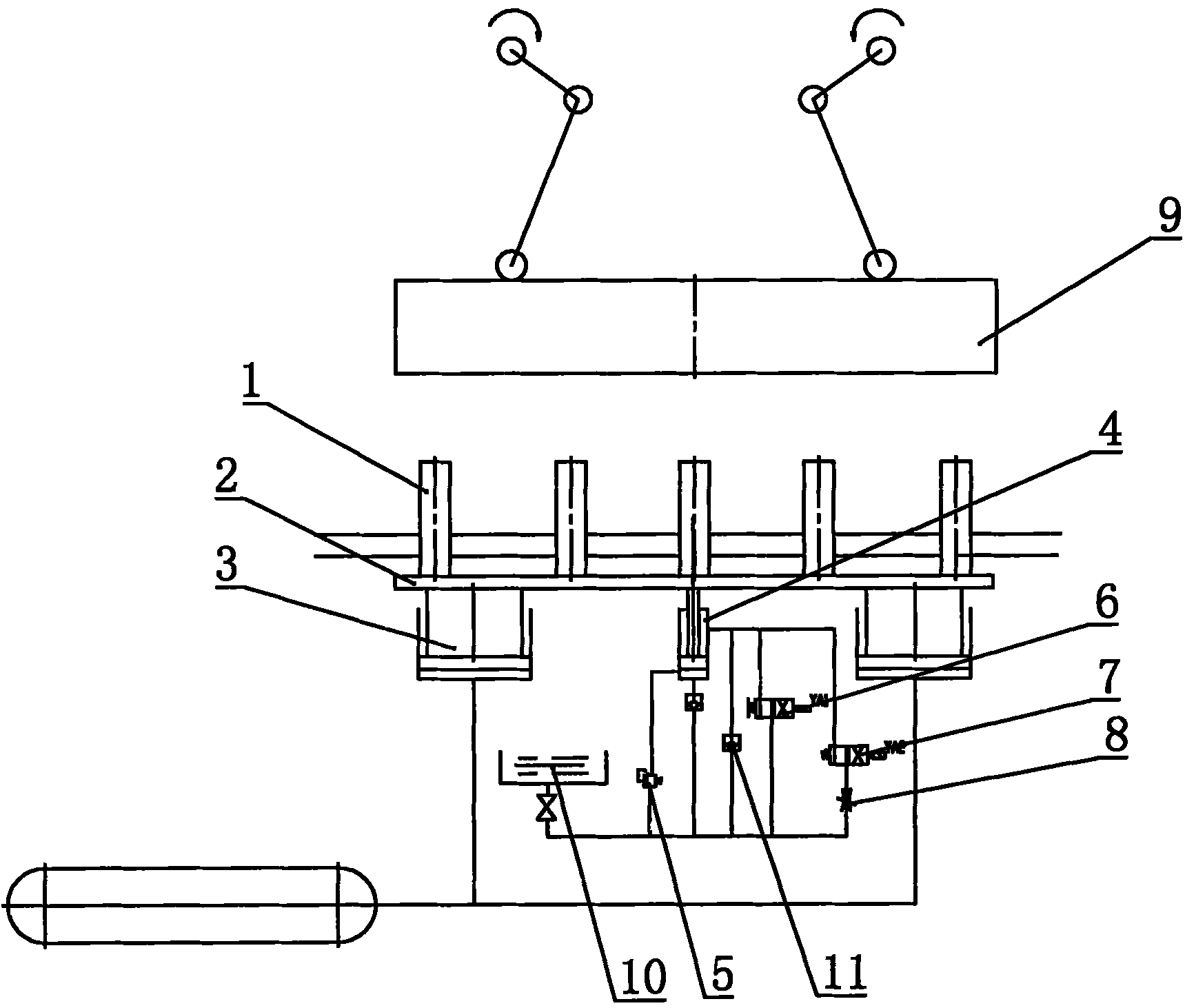
[0010] As shown in the accompanying drawings, it includes the ejector rod supporting plate 2 on which the ejector rod 1 is installed. Above the ejector rod 1, there is a slider 9 that cooperates with it to press and form the workpiece. , also includes a cylinder 3 with a power source, and a hydraulic cylinder 4 without a power source.
[0011] There are two cylinders 3, which are fixed on both sides of the lower end surface of the ejector rod supporting plate 2, and the cylinders 3 are connected with the air compressor air storage tank through a trachea.
[0012] The hydraulic cylinder 4 is arranged between the two cylinders 3, and its piston rod is fixedly connected with the ejector support plate 2. The rod chamber and the rodless chamber of the hydraulic cylinder 4 are respectively connected to the oil tank 10 through the oil pipe, and the oil pipe is connected in series with a filling valve. 11. The rodless chamber of the hydraulic cylinder 4 is connected with a pressurized...
PUM
 Abstract
Description
Claims
Application Information