Yarn winding device

A winding device and yarn technology, which is applied in the directions of transportation and packaging, conveying filamentous materials, and thin material processing, etc., can solve the problem of rising heat generation of the traverse drive device, decreasing specifications of the yarn winding device, and easy to reach the limit. Torque and other problems, to achieve the effect of suppressing the increase in heat generation

Active Publication Date: 2012-01-11
MURATA MASCH LTD
View PDF4 Cites 4 Cited by
  • Summary
  • Abstract
  • Description
  • Claims
  • Application Information

AI Technical Summary

Problems solved by technology

Therefore, even under the same winding conditions, compared with the case where the lead ratio is 1.0, the heat generation of the traverse drive dev...

Method used


Image

  • Yarn winding device
  • Yarn winding device
  • Yarn winding device

Examples


Embodiment Construction

[0023] Embodiments of the invention will be described below using the drawings.

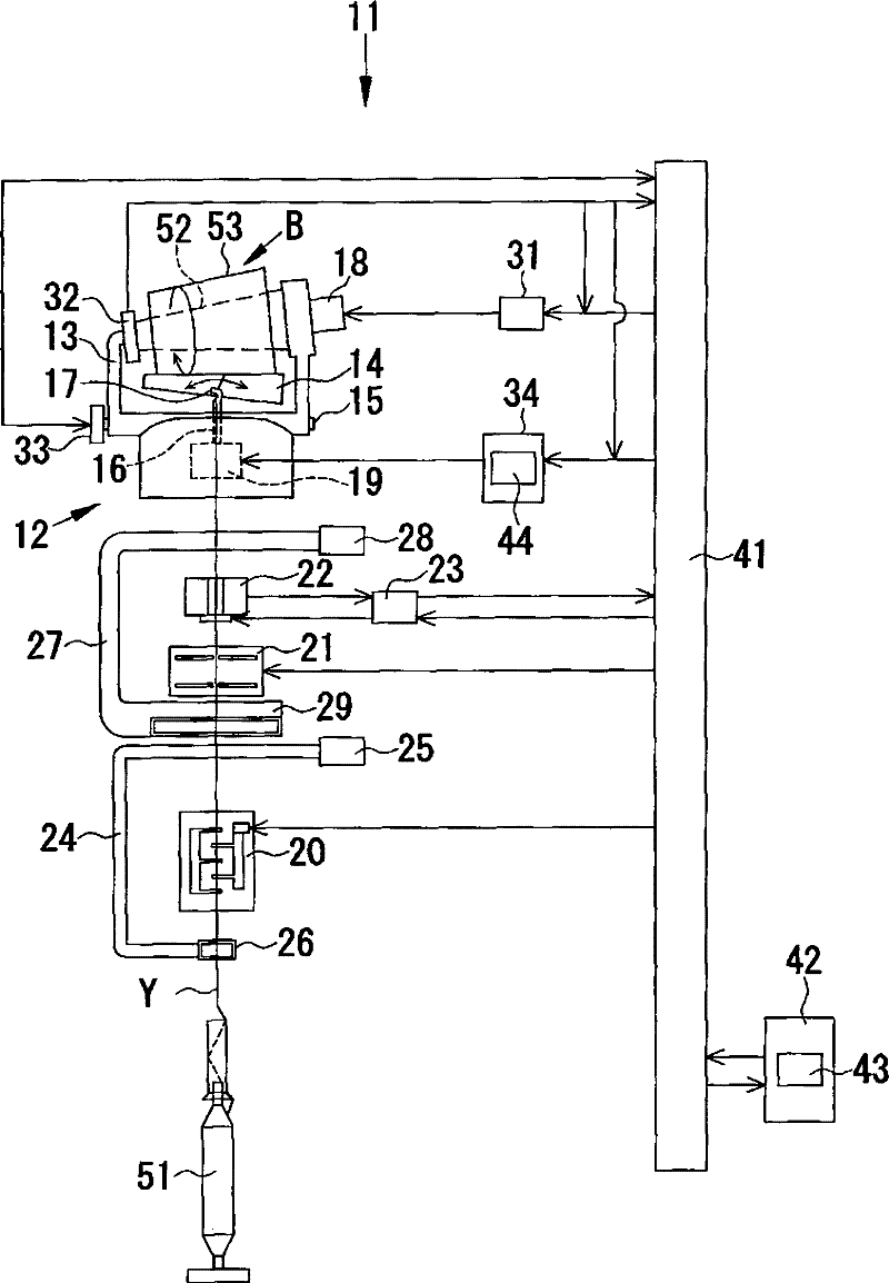
[0024] use Figure 1 to Figure 3 The yarn winding device 11 according to the first embodiment of the present invention will be described.

[0025] like figure 1 As shown, the yarn winding device 11 of this embodiment winds the yarn Y around the winding tube 52 while traversing the yarn Y of the yarn supplying bobbin 51 by the traverse device 12 to form a yarn layer, and further A yarn winding device that produces a tapered package 53. in, figure 1 One yarn winding device 11 is shown, but an automatic winder may be configured by arranging a plurality of such yarn winding devices 11 in parallel.

[0026] In this specification, the winding tube 52 and the package 53 are collectively referred to as a winding bobbin B. As shown in FIG. That is, the winding bobbin B on which the yarn layer is not formed is the winding tube 52 , and the winding bobbin B on which the yarn layer is formed is the pack...


PUM


Abstract

A yarn winding device (11) that produces a conical package (53), includes a traverse guide (17), a traverse driving section (19), a lead ratio setting section (43) adapted to set, as a lead ratio, a value of a ratio of traverse time within a larger diameter region with respect to traverse time within a smaller diameter region of the package (53), or a value of a ratio of traverse speed within the smaller diameter region with respect to traverse time within the larger diameter region of the package, and a speed profile adjusting section (44) adapted to adjust a speed profile of the traverse guide (17) in at least one of the larger diameter region and the smaller diameter region of the package (53) according to the set lead ratio set by the lead ratio setting section (43).

Description

technical field [0001] The present invention relates to a yarn winding device for winding yarn into a winding bobbin. Background technique [0002] Conventionally, in a yarn winding device that winds the yarn into a winding bobbin while traversing the yarn, it is known to traverse the traverse guide when forming a tapered package (package). A yarn winding device in which the speed varies between a small-diameter side region and a large-diameter side region (for example, Japanese Patent Application Laid-Open No. 10-109823). In a tapered package, in order to improve the package shape and unwinding property, the traverse speed in the small diameter side region of the package is set to high speed, and the traverse speed in the large diameter side region of the package is set to low speed. [0003] In a tapered package, the ratio of the traverse speed of the traverse guide at the small diameter side region to the traverse speed of the traverse guide at the large diameter side re...

Claims


Application Information

Patent Timeline
IPC IPC(8): B65H54/28
CPCB65H54/2884B65H54/103B65H2701/31
Inventor 牟田胜文
Owner MURATA MASCH LTD
Why Eureka
Try Eureka