
Hand wheel hydraulic pump

A hydraulic pump and handwheel technology, applied in the field of hydraulic pumps, can solve the problems of high labor intensity, low hydraulic power, and low efficiency, and achieve the effects of reducing labor intensity, improving conversion efficiency, and convenient operation

Inactive Publication Date: 2012-01-11
SHANGHAI RONGDE ENG EQUIP
View PDF6 Cites 2 Cited by
  • Summary
  • Abstract
  • Description
  • Claims
  • Application Information

AI Technical Summary

Problems solved by technology

There are many restrictions in the application of this type of hydraulic pump. The key is that the length of the operating rod and the distribution of the fulcrum must meet the range of motion of the arm, and the position of the fulcrum of the operating rod, the diameter of the cylinder of the piston pump, and the pressure of the hydraulic oil sent must be considered. and flow, while the operating rod must adapt to the amount of human energy
Therefore, in each push and pull process of the operating rod, a single piston cylinder can only provide limited oil volume and oil pressure, and the hydraulic power provided is relatively small, and the efficiency of pushing and pulling the operating rod to generate hydraulic power is very low, and the labor intensity is high. Meet the drive of hydraulic actuators in certain occasions

Method used

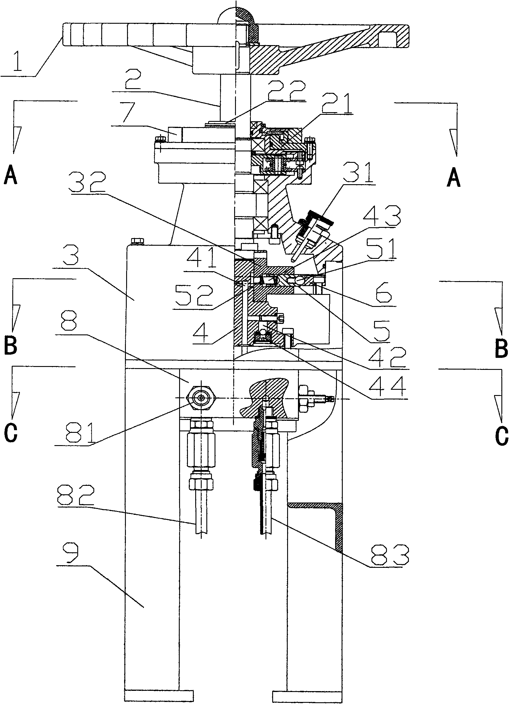
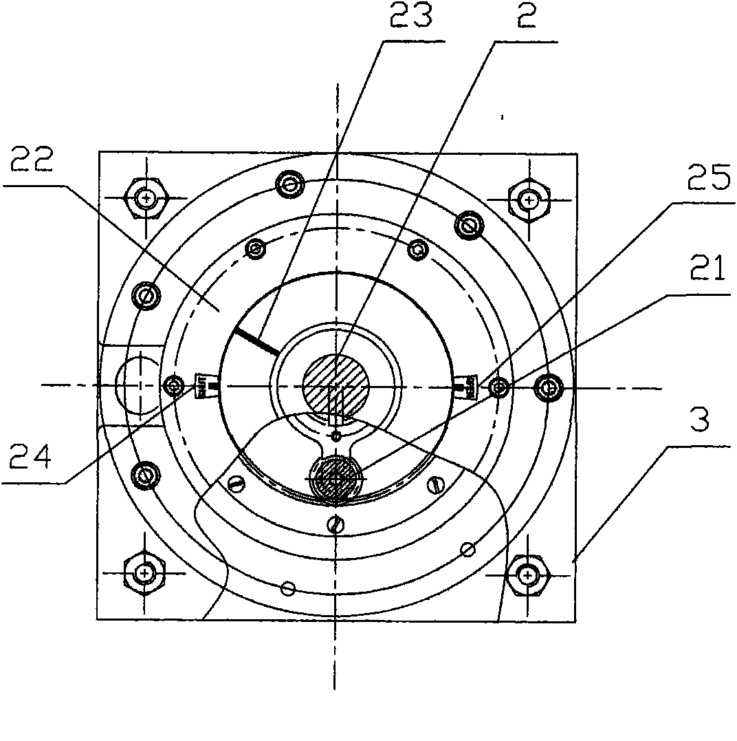
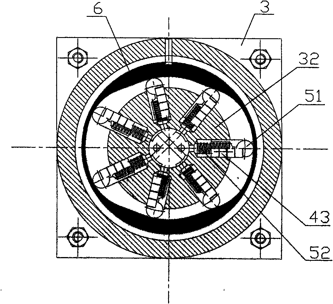

Image

  • Hand wheel hydraulic pump
  • Hand wheel hydraulic pump
  • Hand wheel hydraulic pump

Examples


Embodiment Construction

[0016] like figure 1 and image 3 As shown, the handwheel hydraulic pump of the present invention includes a handwheel 1, a rotating shaft 2, a housing 3 provided with an oil filling port 31, a flow distribution seat 4, a plurality of piston hydraulic cylinders 5, a rotating disk 32, a guide ring 6, a first one-way Valve and the second one-way valve 44, the outer ring of the guide ring 6 is circular, the inner ring is oval and horizontally arranged in the housing 3, the rotating disk 32 is arranged in the housing 3, so The plurality of piston-type hydraulic cylinders 5 are arranged on the turntable 32 at intervals, the rear end of the piston 43 of the piston-type hydraulic cylinder 5 is provided with a spring 52, and the front end is provided with a steel ball 51, and the steel ball 51 is arranged along the guide ring 6. The inner ring slides, the rotating shaft 2 penetrates the housing 3 and one end is connected to the center of the turntable 32, and the other end is connect...


PUM


Abstract

The invention discloses a hand wheel hydraulic pump. A guide ring of which the outer ring is circular and the inner ring is oval and a rotary disk are arranged in a shell of the hand wheel hydraulic pump; the shell is provided with an oil injection port; a plurality of piston hydraulic cylinders are uniformly arranged on the rotary disk at intervals; the back end of a piston of the piston hydraulic cylinder is provided with a spring; the front end of the piston is provided with a steel ball which slides along the inner ring of the guide ring; a rotary shaft is inserted into the shell; one end of the rotary shaft is connected with the center of the rotary disk, and the other end of the rotary shaft is connected with a hand wheel; a flow distribution seat is arranged in the shell, and is provided with a plurality of oil grooves which are communicated with the hydraulic cylinders and two oil ports passing out of the shell; the two oil ports of the flow distribution seat are communicated with the oil grooves and the output ends of two one-way valves respectively; and the input ends of the two one-way valves are communicated with the shell. The hand wheel hydraulic pump has the advantages of convenience for operating, capabilities of supplying sufficient hydraulic power, greatly lowering the labor intensity and improving the conversion efficiency of labor force and hydraulic power, and suitability of driving hydraulic executing elements under multiple working conditions.

Description

technical field [0001] The invention relates to a hydraulic pump, in particular to a hand wheel hydraulic pump. Background technique [0002] In the hydraulic system, the hydraulic pump is used to drive the hydraulic actuators. Commonly used manually operated hydraulic pumps use the principle of leverage. Push and pull the operating rod back and forth by hand to drive a suction-type small piston pump at the other end of the operating rod. The small piston Pumps generate the pressure and flow of fluid, converting human power into hydraulic power. This is what is commonly called a pressure rod hydraulic hand pump. There are many restrictions in the application of this type of hydraulic pump. The key is that the length of the operating rod and the distribution of the fulcrum must meet the range of motion of the arm, and the position of the fulcrum of the operating rod, the diameter of the cylinder of the piston pump, and the pressure of the hydraulic oil sent must be considere...

Claims


Application Information

Patent Timeline
Patent Type & Authority Applications(China)
IPC IPC(8): F15B15/00
Inventor 冯晓明
Owner SHANGHAI RONGDE ENG EQUIP
Learn More