
Light path alignment device of laser interferometer and method

A laser interferometer and laser technology, applied in the field of lithography, can solve the problems of affecting the service life of the optical fiber, difficult disassembly and assembly of the optical fiber receiving head, and easy damage

Active Publication Date: 2012-01-11
SHANGHAI MICRO ELECTRONICS EQUIP (GRP) CO LTD
View PDF6 Cites 16 Cited by
  • Summary
  • Abstract
  • Description
  • Claims
  • Application Information

AI Technical Summary

Problems solved by technology

However, when the position of the interferometer or the measuring mirror changes, the coincidence of the reference spot and the measuring spot will change, and it is necessary to readjust the coincidence of the reference spot and the measuring spot. At this time, the optical fiber receiving head must be removed
On the one hand, due to the limitation of the installation space of the interferometer, it is very difficult to disassemble and assemble the fiber receiving head, especially when it is applied in a scene with a small space such as a lithography machine; However, the optical fiber is easily damaged by frequent plugging and unplugging, which affects the service life of the optical fiber.

Method used


Image

  • Light path alignment device of laser interferometer and method
  • Light path alignment device of laser interferometer and method
  • Light path alignment device of laser interferometer and method

Examples


Embodiment Construction

[0025] In the following, preferred embodiments according to the present invention will be described in detail with reference to the accompanying drawings. For the convenience of describing and highlighting the present invention, relevant components existing in the prior art are omitted from the drawings, and the description of these known components will be omitted.

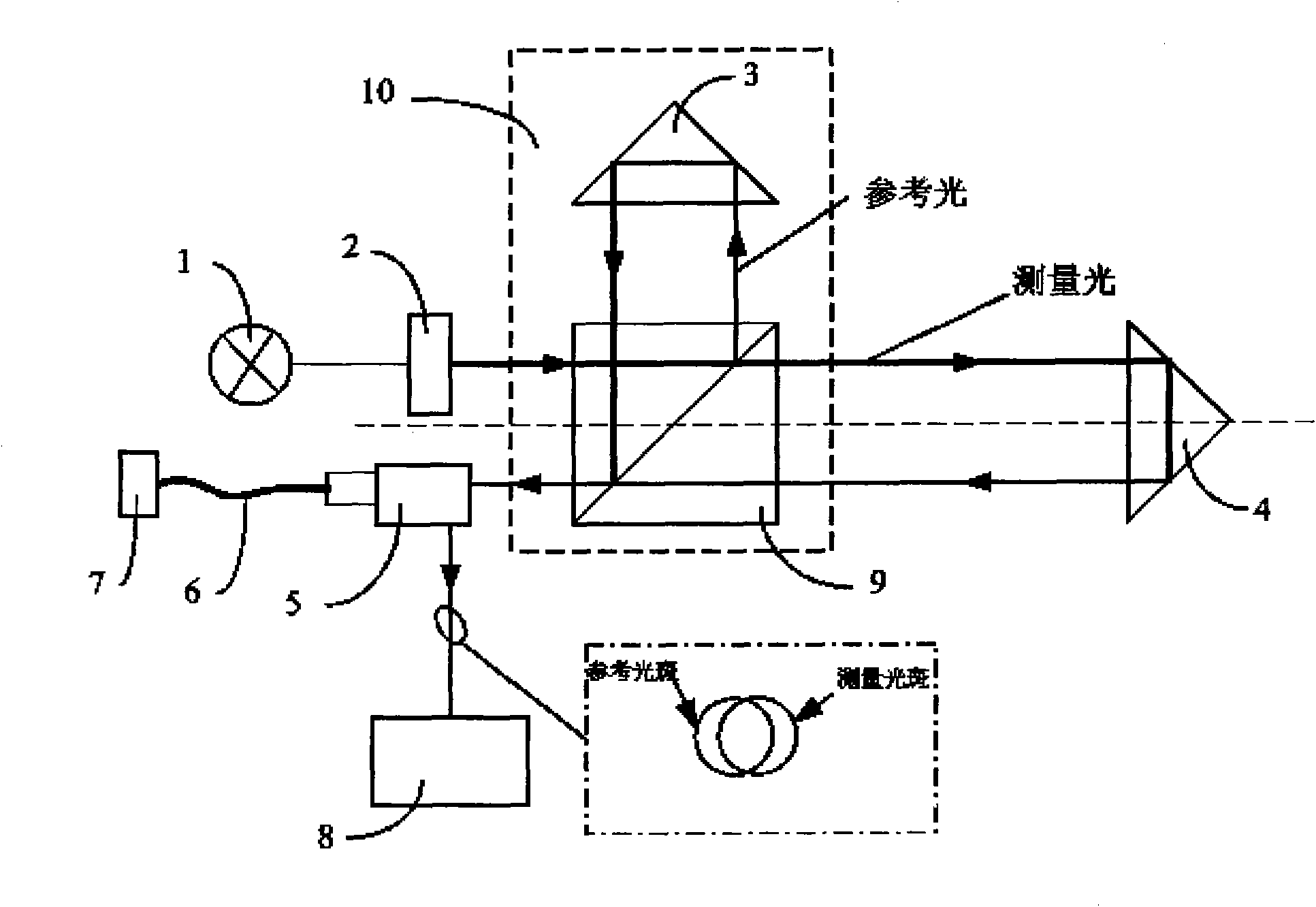
[0026] The invention provides a laser interferometer optical path alignment device, which is used for conveniently observing the coincidence degree of the reference light spot and the measurement light spot of the outgoing light of the laser interferometer. The structure of the alignment device is as figure 1 As shown, the laser light emitted by the laser 1 enters the laser interferometer 10 after passing through the mirror adjustment mechanism 2. The laser interferometer 10 includes a polarization beam splitter 9 and a reference mirror 3, and the incident laser light is divided into reference light by the polar...


PUM


Abstract

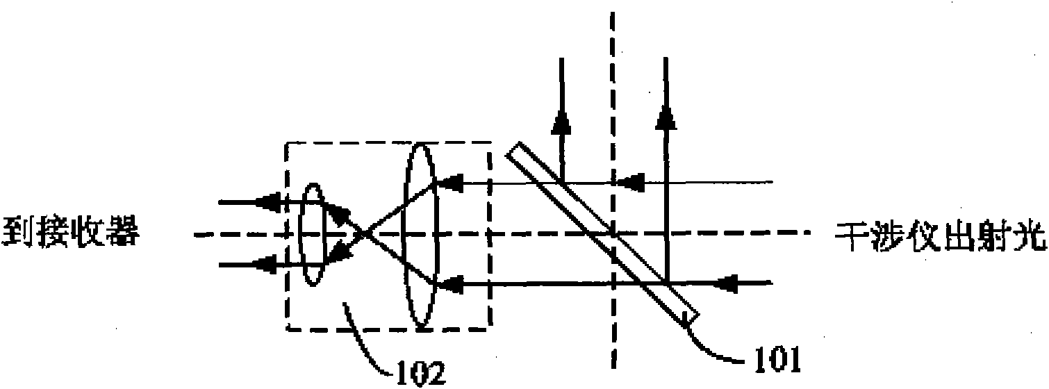
The invention relates to a light path alignment device of a laser interferometer and a method. Laser emitted by a laser device is adjusted by a reflective mirror adjusting mechanism and is then transmitted into the laser interferometer, a polarization beam-splitting mirror divides the laser into reference light and measurement light, the reference light is reflected by a reference reflective mirror, the measurement light is reflected by a measurement reflective mirror, is transmitted to the polarization beam-splitting mirror and is then reflected by the polarization beam-splitting mirror to the optical fiber receiving head, and the beam-splitting mirror divides incident light into two parts, wherein the majority of the light is compressed by a compression lens component in the optical fiber receiving head and is transmitted to a receiver, and the rest of the light is projected to a light spot observation device for observation of overlapping of a reference light spot and a measurementlight spot.

Description

technical field [0001] The invention relates to the field of lithography, in particular to an interferometer optical path alignment device used for a lithography device. Background technique [0002] At present, laser interferometry has been widely used in high-precision position measurement, which has the characteristics of high precision, strong reliability, and small error interference. The alignment accuracy of the optical path of the laser interferometer will directly affect the measurement accuracy and measurement range of the interferometer. [0003] Agilent and Zygo companies in the United States proposed that the alignment accuracy of the optical path of the interferometer is mainly to observe the coincidence of the reference spot and the measurement spot in the exit spot of the interferometer. The traditional method is to adjust the laser or reflector without installing the optical fiber receiving head, and then install the image 3 The fiber optic receiver shown ...

Claims


Application Information

Patent Timeline
IPC IPC(8): G01B9/02G03F7/20
Inventor 鲁武旺陈飞彪李志丹金小兵
Owner SHANGHAI MICRO ELECTRONICS EQUIP (GRP) CO LTD
Learn More