
Liquid crystal display (LCD) driving circuit, data driving chip, liquid crystal panel and liquid crystal display device

A technology for data-driven chips and liquid crystal display devices, applied in static indicators, nonlinear optics, optics, etc., can solve the problems of enlarged space, reduced space of winding 3, uneven display of COF control area 1, etc. The effect of wiring space and cost reduction

Inactive Publication Date: 2012-01-11
TCL CHINA STAR OPTOELECTRONICS TECH CO LTD
View PDF4 Cites 27 Cited by
  • Summary
  • Abstract
  • Description
  • Claims
  • Application Information

AI Technical Summary

Problems solved by technology

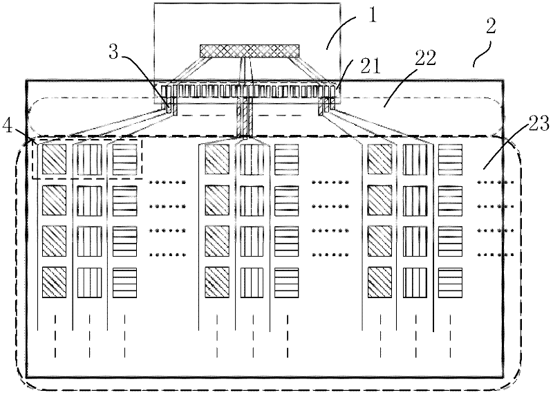
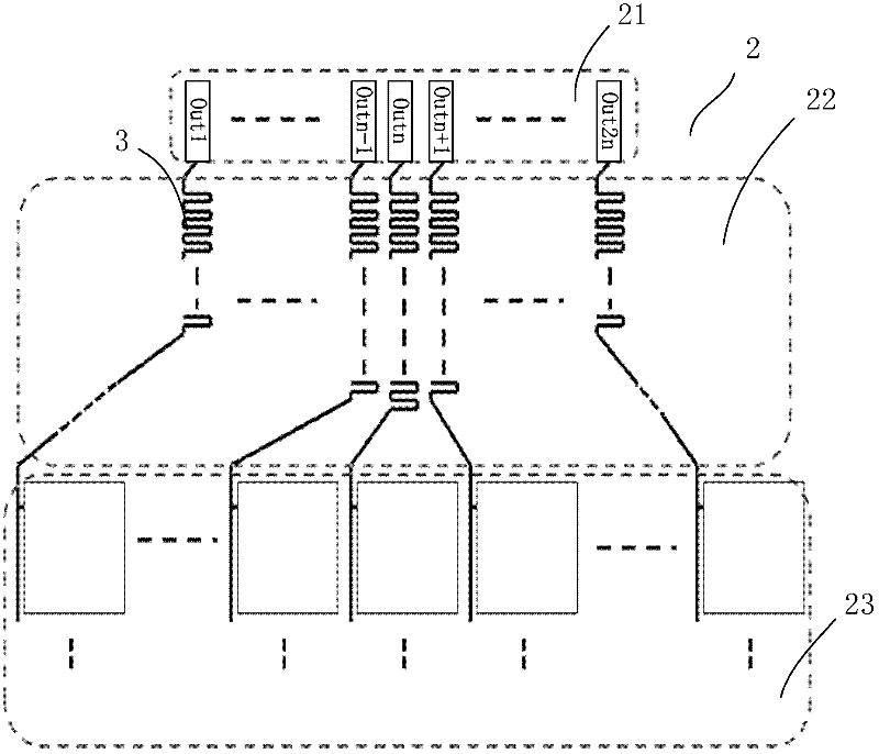
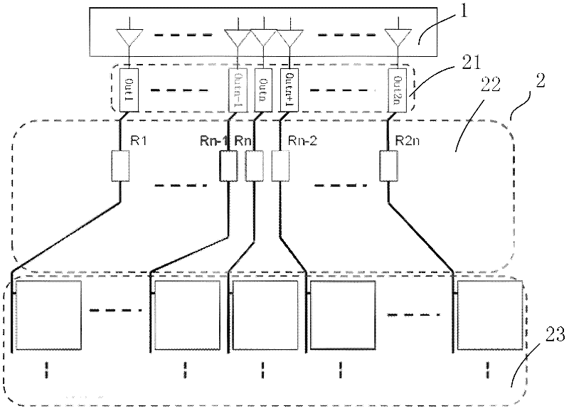
like image 3 , the serpentine winding 3 of each channel in the glass substrate winding 3 area is regarded as each equivalent resistance, and these equivalent resistances will be matched and equal: R1=R2=...=Rn-1=Rn=Rn+ 1=....=R2n, at this time, the impedance of each row of data is the same, when all output channels are turned on at the same time to provide voltage to the pixel 4, the charging time for each pixel point of the same row is the same, In this way, the uniformity of the picture will be better. On the contrary, when the impedance design is inconsistent, the charging time of each pixel 4 in the same row will be different, and the display of the COF control area 1 will have uneven problems.
However, with the increase in the number of output channels of a single COF, the space required for impedance matching with serpentine lines will become larger (to meet output compensation), and the current development trend of the frame is to develop in the direction of a narrow frame. 3 The space gradually shrinks

Method used


Image

  • Liquid crystal display (LCD) driving circuit, data driving chip, liquid crystal panel and liquid crystal display device
  • Liquid crystal display (LCD) driving circuit, data driving chip, liquid crystal panel and liquid crystal display device
  • Liquid crystal display (LCD) driving circuit, data driving chip, liquid crystal panel and liquid crystal display device

Examples


Embodiment Construction

[0023] The present invention will be further described below in conjunction with the accompanying drawings and preferred embodiments.

[0024] Such as Figure 4~5 As shown, the liquid crystal panel of the liquid crystal display device includes a kind of LCD driving circuit, and the LCD driving circuit includes a data driving chip with multiple output terminals, and a plurality of data lines respectively connected to the output terminals of the data driving chip. There is also an output resistor between the output terminal of the data driver chip and each data line, the equivalent resistance of the multiple data lines is not the same, the equivalent resistance of each data line and the corresponding The sum of the output resistances mentioned above is equal. The data driver chip can be selected in COG mode (that is, the data driver chip is directly bound on the film material and connected to the lead wire set on the LCD pressing area) or COF (the data driver chip is set on the...


PUM


Abstract

The invention discloses a liquid crystal display (LCD) driving circuit, a data driving chip, a liquid crystal panel and a liquid crystal display device. The LCD driving circuit comprises the data driving chip which is provided with a plurality of output ends, and a plurality of data cables which are respectively connected with the output ends of the data driving chip; an output resistor is respectively arranged between each output end of the data driving chip and each data cable; not all the equivalent resistance of the data cables is the same; and the equivalent resistance of each data cable and the sum of the corresponding output resistors is equal. According to the invention, because the output resistors are adopted to replace snake-shaped windings, the widths that the output resistors occupy are smaller than those of the snake-shaped windings, a wiring space of a glass substrate can be reduced, and the design of a narrow frame is realized; and in addition, because more data cables can be laid in the frame with a unit of width, the cost can be reduced.

Description

technical field [0001] The invention relates to the field of liquid crystal display, and more specifically relates to an LCD driving circuit, a data driving chip, a liquid crystal panel and a liquid crystal display device. Background technique [0002] At present, when the data line in the LCD glass is output from the data driver chip, in order to make the impedance of the line at each pixel 4 basically the same, it will be realized by using a serpentine line, such as figure 1 As shown, the golden finger 21 of the COF (data-driven chip pressed on the film material) 1 will be pressed to the lead wire of the glass substrate 2, and then connected to the pixel 4 of the glass substrate after a winding wire 3, figure 2 It is an enlarged schematic diagram of winding 3, the purpose is to make the resistance of all outputs match. Such as image 3 , the serpentine winding 3 of each channel in the glass substrate winding 3 area is regarded as each equivalent resistance, and these eq...

Claims


Application Information

Patent Timeline
Patent Type & Authority Applications(China)
IPC IPC(8): G02F1/133
CPCG02F1/133G02F1/1345
Inventor 郭东胜
Owner TCL CHINA STAR OPTOELECTRONICS TECH CO LTD
Learn More