
Motor vector control method based on Hall position sensor

A vector control, Hall position technology, applied in vector control systems, motor generator control, electronic commutation motor control, etc., can solve the problems of motor torque fluctuation, current waveform distortion, inability to realize motor speed regulation, etc., to achieve smooth The effect of speed regulation

Active Publication Date: 2012-01-11
WANXIANGQIANCHAO CO LTD
View PDF2 Cites 22 Cited by
  • Summary
  • Abstract
  • Description
  • Claims
  • Application Information

AI Technical Summary

Problems solved by technology

[0003] When the back electromotive force of the motor is a sine wave, if the DC brushless control method is adopted, because the control voltage waveform of the motor is a square wave, the square wave is inconsistent with the waveform of the back electromotive force of the motor, which will cause distortion of the current waveform and make the motor torque fluctuate. Unable to achieve smooth speed regulation of the motor

Method used


Image

  • Motor vector control method based on Hall position sensor
  • Motor vector control method based on Hall position sensor
  • Motor vector control method based on Hall position sensor

Examples


Embodiment approach

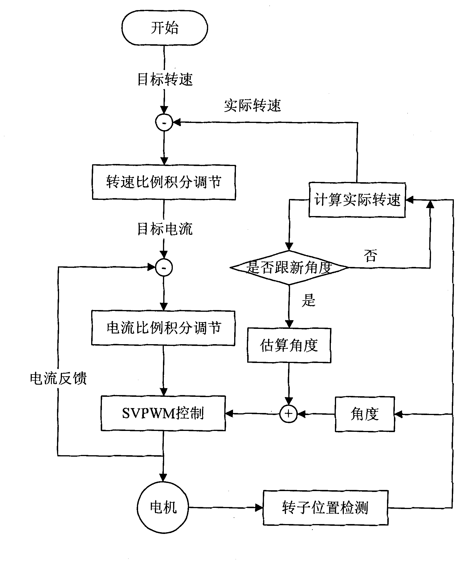
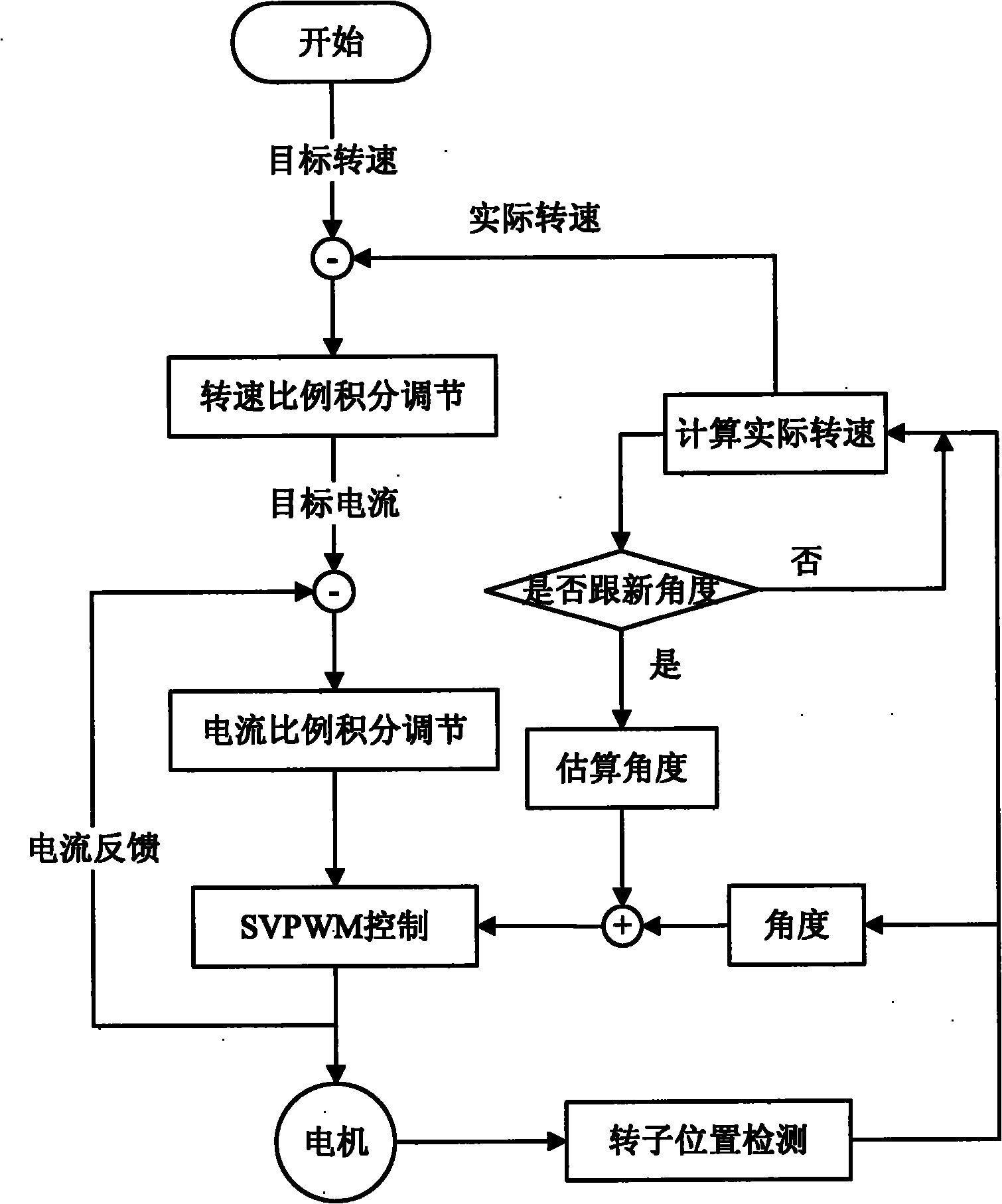
[0030] According to one embodiment of the present invention, as figure 1 Shown, a kind of motor vector control method based on Hall position sensor, wherein, this motor vector control method comprises the following steps:

[0031] 1) Given a target speed, the actual speed of the motor is calculated according to the detection signal of the Hall position sensor, and the proportional integral adjustment is performed to control the given current according to the speed difference between the target speed and the actual speed;

[0032] 2) Perform proportional integral adjustment according to the given current and the actual feedback current to obtain the required given voltage value;

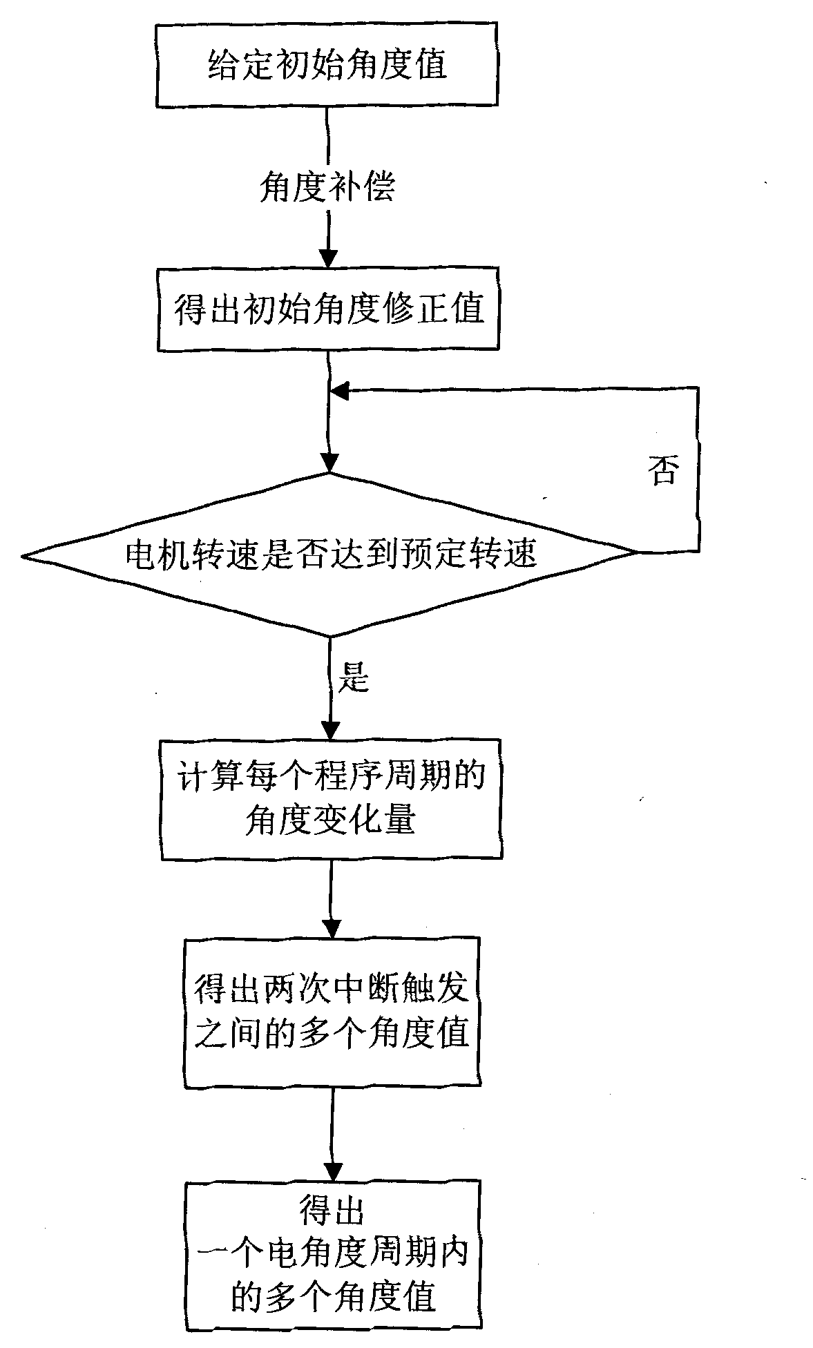
[0033] 3) Calculate multiple angle values ​​within one electrical angle cycle, and perform SVPWM control according to the calculated multiple angle values ​​and a given voltage value to realize vector control of the motor.

[0034] in the attached figure 1 Among them, "-" means the difference betwee...


PUM


Abstract

The invention relates to a motor vector control method based on a Hall position sensor, comprising the following steps of: giving a target rotating speed, calculating an actual rotating speed of a motor according to a detecting signal of the Hall position sensor, and carrying out proportional-integral adjustment according to the rotating speed difference of the target rotating speed and the actual rotating speed to control the given current; carrying out proportional-integral adjustment according to the given current and the feedback actual current to obtain a needed given voltage value; and calculating a plurality of angle values in one electrical angle period, and carrying out SVPWM (Space Vector Pulse Width Modulation) control according to the calculated angle values and the given voltage value to realize vector control on the motor. In the motor vector control method based on the Hall position sensor, by vector control on the motor, the three-phase output voltage is close to sine wave, and the stable speed adjustment for the motor is realized.

Description

technical field [0001] The invention relates to a motor vector control method based on a Hall position sensor. Background technique [0002] Synchronous motors generally use rotary transformers as position detection devices. Due to the high price of rotary transformers, some motors also use Hall position sensors to sample position signals. The control method adopts DC brushless control method, which is based on the back electromotive force of the motor The case where the waveform is a trapezoidal wave. [0003] When the back electromotive force of the motor is a sine wave, if the DC brushless control method is adopted, because the control voltage waveform of the motor is a square wave, the square wave is inconsistent with the waveform of the back electromotive force of the motor, which will cause distortion of the current waveform and make the motor torque fluctuate. Unable to achieve smooth speed regulation of the motor. Contents of the invention [0004] In order to so...

Claims


Application Information

Patent Timeline
Patent Type & Authority Applications(China)
IPC IPC(8): H02P21/00H02P21/14H02P6/16H02P21/22
Inventor 杜智勇周永庄陈焕龙
Owner WANXIANGQIANCHAO CO LTD
Learn More