
Squelch control method of automatic gain power amplifier chain and circuit

An automatic gain and squelch control technology, applied in gain control, amplification control, electrical components and other directions, can solve the problems of small squelch input signal, single detection purpose, difficult to guarantee threshold value, etc. Low cost and improved noise suppression sensitivity

Active Publication Date: 2012-01-11
BEIJING BBEF SCI & TECH
View PDF5 Cites 9 Cited by
  • Summary
  • Abstract
  • Description
  • Claims
  • Application Information

AI Technical Summary

Problems solved by technology

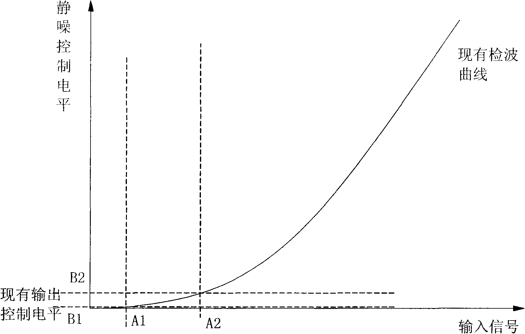
[0006] 1. Since the wave detector is directly detected at the input end, the squelch input signal is small, and the wave detector will work in the non-linear region of the small signal (such as image 3 As shown), the detection effect is relatively slow, and the threshold value is difficult to guarantee, especially when the temperature variation range is large, the squelch point variation range is large, and a window area will appear
[0007] 2. Since the detection circuit is added to the input end of the power amplifier chain, the detected signal only reflects the signal size of the input end, and has no connection with the circuit in the power amplifier chain afterwards, so the detection purpose is single
[0008] 3. It is necessary to add a detection circuit separately, which increases the cost of the equipment and increases the volume of the equipment

Method used


Image

  • Squelch control method of automatic gain power amplifier chain and circuit
  • Squelch control method of automatic gain power amplifier chain and circuit
  • Squelch control method of automatic gain power amplifier chain and circuit

Examples


Embodiment Construction

[0040] The aforementioned and other technical contents, features and effects of the present invention will be clearly presented in the following detailed description of preferred embodiments with reference to the drawings. Through the description of the specific implementation mode, when the technical means and functions adopted by the present invention to achieve the predetermined purpose can be obtained a deeper and more specific understanding, but the accompanying drawings are only for reference and description, and are not used to explain the present invention be restricted.

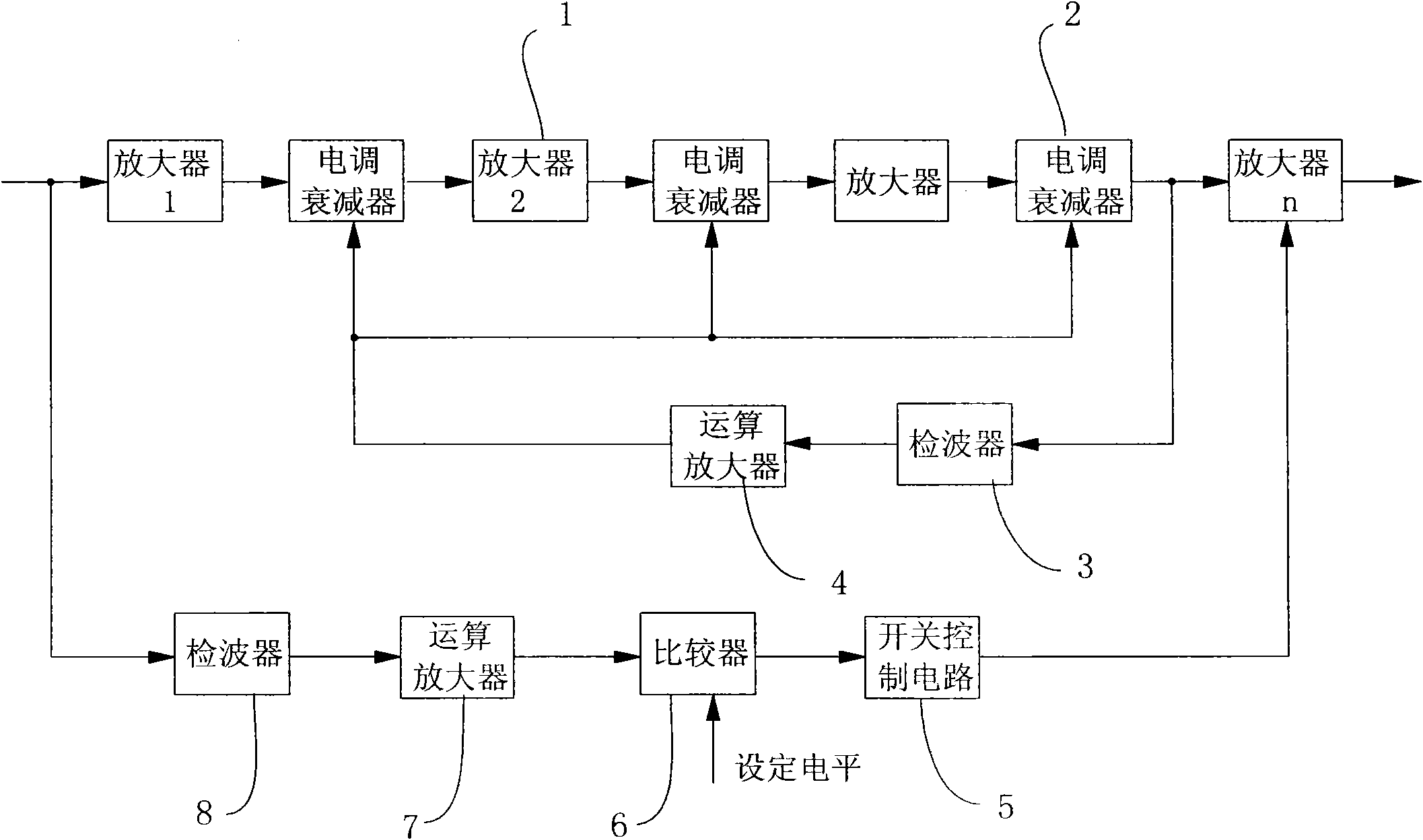
[0041] see Figure 4 , Figure 5 As shown, a kind of automatic gain power amplifier chain squelch control method provided by the present invention, described automatic gain power amplifier chain comprises n series amplifiers 11, is arranged on the electrical adjustment attenuator 12 between adjacent two amplifiers 11 and by the detection The automatic gain control loop formed by device 13 and opera...


PUM


Abstract

The invention relates to a squelch control circuit, in particular to a squelch control method of an automatic gain power amplifier chain and a circuit. The method comprises the following steps of: (1) sampling an input signal of nth amplifier in the automatic gain power amplifying chain; (2) detecting the input signal into a direct-current voltage signal; (3) carrying out negative feedback amplification on the direct-current voltage signal; (4) comparing the direct-current voltage signal through the negative feedback amplification with a direct-current voltage with preset squelch ratio; and (5) if the direct-current voltage signal is more than or equal to the direct-current voltage with the preset squelch ratio, controlling the power amplifying chain to disconnect; if the direct-current voltage signal is less than the direct-current voltage with the preset squelch ratio, controlling the power amplifying chain to connect. In the invention, a direct-current control signal sent to an electric control attenuator is used as a squelch signal, and a detection circuit does not need to be arranged independently; and since the negative feedback amplification is carried out on the direct-current control signal, a characteristic curve of a detector is justly overturned, so that the problems that a judgment window area of the existing squelch control circuit is too narrow and non-linear are overcome, and the squelch sensitivity is greatly improved.

Description

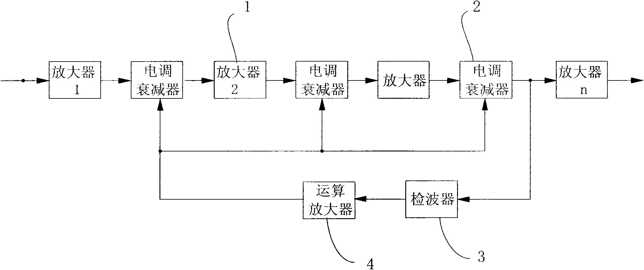
technical field [0001] The invention relates to a squelch control circuit, in particular to a squelch control method and circuit for an automatic gain power amplifier chain in wireless transmission equipment such as communication, radio and television, so as to protect the final power amplifier. Background technique [0002] With the advancement of science and technology, the number and types of transmission equipment used in wireless transmission fields such as communications, radio and television are increasing. Most systems use high-gain power amplifier chains with AGC (Automatic Gain Control) to achieve output power. Stablize. This high-gain power amplifier chain with automatic gain control includes n series amplifiers 1, an electric-adjustable attenuator 2 arranged between two adjacent amplifiers, and a control circuit composed of a detector 3 and a negative feedback amplifier 4. The automatic gain control loop of attenuator 2 (as figure 1 shown), the control signal o...

Claims


Application Information

Patent Timeline
Patent Type & Authority Applications(China)
IPC IPC(8): H03G3/20
Inventor 张宇栾鹤峰卜宁
Owner BEIJING BBEF SCI & TECH
Learn More