
Tube pump

A technology of hose pumps and hoses, applied in the field of hose pumps, can solve the problems of complex structure, complicated handling and management of tubes, complicated fixing operations, etc., and achieve the effects of reducing manufacturing costs, simplifying structures, and preventing misalignment

Active Publication Date: 2014-08-13
NIPRO CORP +1
View PDF9 Cites 5 Cited by
  • Summary
  • Abstract
  • Description
  • Claims
  • Application Information

AI Technical Summary

Problems solved by technology

Therefore, in the hose pumps described in Patent Documents 1 and 2, the structure of the mold for producing the connector becomes complicated, and furthermore, there is a problem that the manufacturing cost of the hose pump becomes high.
[0012] On the other hand, in the aforementioned Patent Documents 3 and 4, since the bracket is fixed in advance in a state perpendicular to the pipe, such fixing work is complicated.
Furthermore, care must be taken not to dispose of a plurality of hoses after the brackets are attached without being entangled with the brackets of other hoses, so there is a disadvantage that the handling and management of the tubes becomes complicated.

Method used


Image

  • Tube pump
  • Tube pump
  • Tube pump

Examples


Embodiment Construction

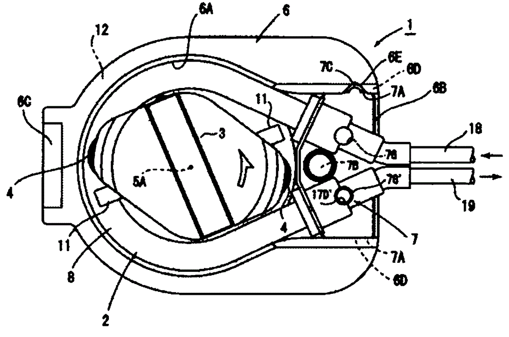
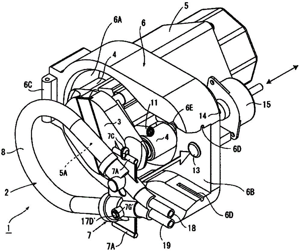
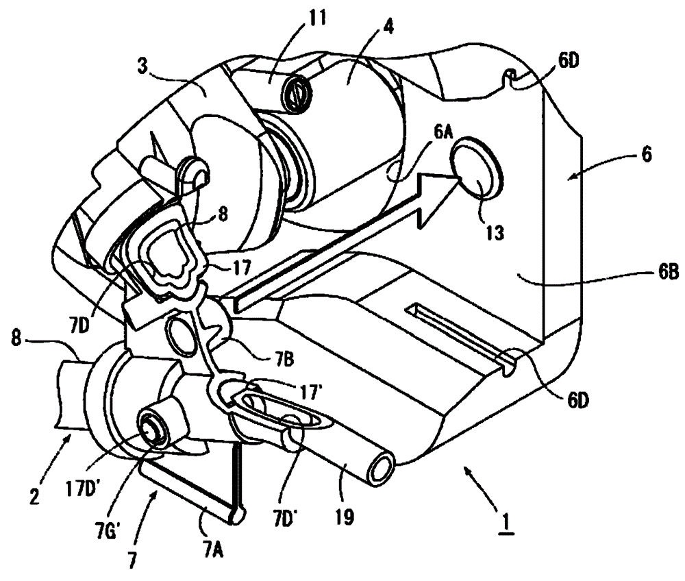
[0029] Hereinafter, the present invention will be described with respect to the illustrated embodiments, in Figure 1 to Figure 3 Among them, 1 is a hose pump, and this hose pump 1 operates a catheter 2 made of a soft hose through the rollers 4 and 4 of the rotor 3 to transport liquid (blood). The hose pump 1 is used as a blood pump of the dialysis device, and is installed on the front of the main body of the dialysis device. figure 1 A front view showing a hose pump 1 provided on the front of the main body of the dialysis device, figure 2 It is a perspective view of the hose pump 1 .

[0030] The hose pump 1 of the present embodiment includes: a motor 5 disposed on the main body of the dialysis device and supported such that a drive shaft 5A is horizontal; and a rotor 3 whose center is connected to the The front end of the drive shaft 5A of the motor 5, and rotates on the vertical plane with the drive shaft 5A as the center of rotation; the casing 6 surrounds the rotor 3 a...


PUM


Abstract

The conduit (2) of the hose pump (1) has: a loop-shaped large-diameter hose (8); a supply hose (18) connected to the end of the large-diameter hose (8) One end; the discharge hose (19), which is connected to the other end of the large diameter hose (8) by a discharge side connector (17'). The bracket (7) has a pair of stepped engaging recesses (7D, 7D') capable of engaging with the outer surfaces of the two connectors (17, 17'). The two connectors (17, 17') are held by the stepped engagement recesses (7D, 7D') of the bracket (7), and the bracket (7) in this state is mounted on the cutout (6B) of the housing (6). . It is possible to provide a hose pump (1) in which the conduit (2) is easily attached to and detached from the housing (6).

Description

technical field [0001] The present invention relates to a hose pump and, more particularly, to improvements in hose pumps for delivering fluids such as blood or saline. Background technique [0002] Conventionally, a hose pump is known in which a hose is operated by a rotating rotor to deliver a liquid. In particular, the hose pump is used as a blood pump and a rehydration pump of a dialysis device used for dialysis treatment. [0003] In a dialysis apparatus using such a hose pump, installation and removal work of the hose pump and a hose attached to the dialyzer are required before and after dialysis treatment is started. Furthermore, since the order and direction of attaching the hoses to the hose pump are determined for the blood circuit constituted by a plurality of tubes, the work of attaching and detaching the blood circuit to the hose pump is complicated. [0004] Therefore, in order to simplify such cumbersome work, it has been proposed to attach a hose to a pump c...

Claims


Application Information

Patent Timeline
Patent Type & Authority Patents(China)
IPC IPC(8): F04C5/00
CPCF04B43/1261F04B43/0072A61M60/109A61M60/279A61M1/14A61M2205/14
Inventor 园田善之柳本洋二山口晃伸泽田利春伊东洋一
Owner NIPRO CORP
Learn More