
Processing method of valve body

A processing method and valve body technology, applied in the field of valve body processing, to achieve the effects of easy operation, overcoming air holes, and saving material consumption

Inactive Publication Date: 2012-01-18
陈国强
View PDF4 Cites 15 Cited by
  • Summary
  • Abstract
  • Description
  • Claims
  • Application Information

AI Technical Summary

Problems solved by technology

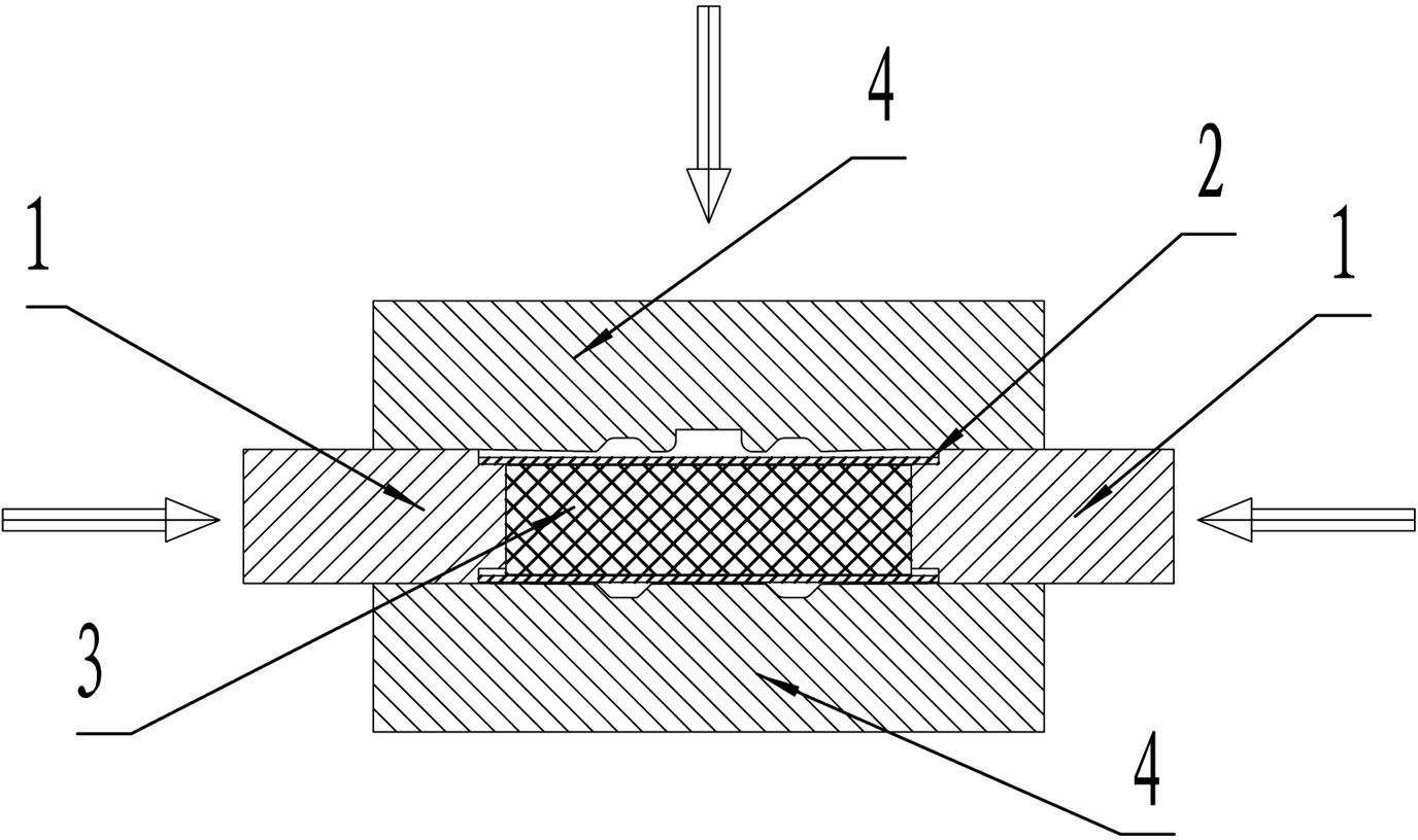
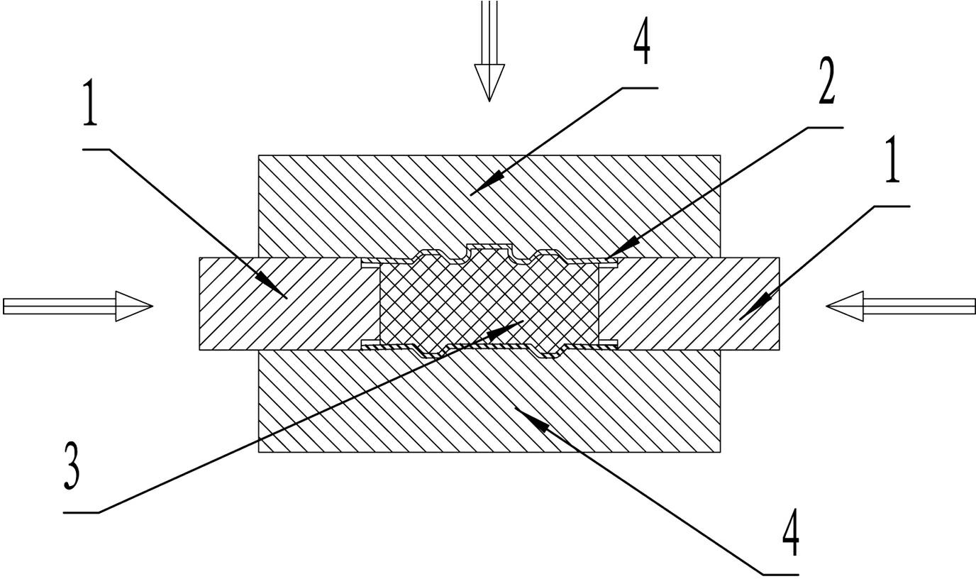
[0005] Because the technical solution above is mainly to use the thin metal tube to expand and extrude through the inner cavity, and at the same time, the two ends of the tube are extruded to form the basic shape of the valve body, and the elastomer column in the thin metal tube is preset to play a good role in the conversion axis. The extrusion force is the effect of radial expansion extrusion force. The elastomer column can be reused many times. The structure of the push rod head can make the thin metal tube be formed effectively and reliably, and the thin metal tube is radially extruded at the same time. The effect of force and axial extrusion force makes the thin metal tube have the effect that the tube wall of the part with small radial deformation is thickened during the forming process, and the tube wall of the part with large radial deformation is basically unchanged. Therefore, the scheme of the present invention Compared with the precision casting process of the valve body, it obviously has the characteristics of simple process, easy operation and stable quality of the finished product. The wall thickness reaches one-third of the minimum wall thickness of the workpiece obtained by the original process. Compared with the prior art, the leaping technical solution proposed by the present invention saves metal raw materials, labor force, and power consumption and material consumption required for precision casting. have made significant progress

Method used


Image

  • Processing method of valve body
  • Processing method of valve body
  • Processing method of valve body

Examples


Embodiment Construction

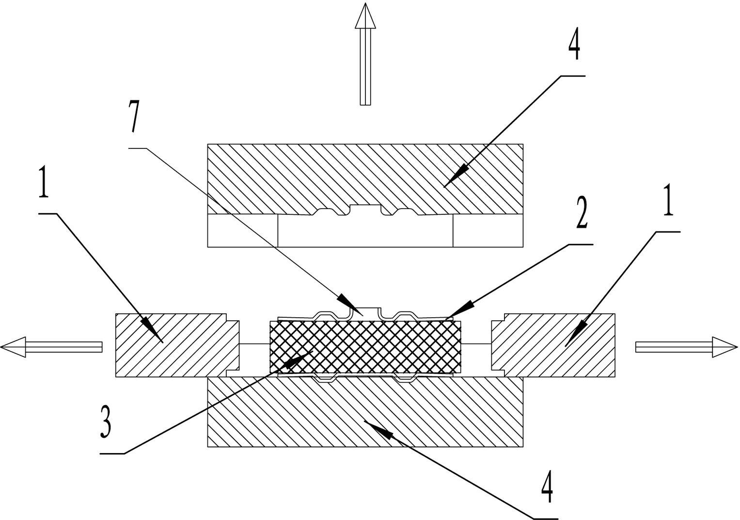
[0011] Such as figure 1 , figure 2 , image 3 , Figure 4 As shown, the specific implementation of the processing method of a valve body provided by the present invention is as follows: A. intercept a section of thin-walled metal pipe 2, the two ends of the thin-walled metal pipe 2 are smooth, and the cylindrical surface of the thin-walled metal pipe 2 has no gaps , and prepare the mold 4, the two ports open to both sides after the mold 4 is closed, and the inner cavity contour of the mold 4 is corresponding to the outer contour of a valve after the mold 4 is closed; B. Put it into the thin-walled metal pipe 2 Elastomer column 3, the mold 4 is opened and put into the thin-walled metal tube 2 with the elastic body column 3, the positions of the two ends of the thin-walled metal tube 2 correspond to the positions of the mold 4 after mold closing Two ports, and the two end faces of the thin-walled metal pipe 2 do not exceed the end faces of the two ports of the mold 4; C. ins...


PUM


Abstract

The invention provides a processing method of a valve body, which comprises the following steps of: A, cutting out a section of thin-wall metal tube (2); B, placing an elastic body column (3) in the thin-wall metal tube (2); C, respectively inserting a propelling rod (1) in two ports of a die (4) which is arranged in the thin-wall metal tube (2); D, driving the two propelling rods (1) towards two sides of the thin-wall metal tube (2), wherein in the propelling process, pre-compressing two end surfaces of the elastic body column (3) in the thin-wall metal tube (2) by using two end surfaces of two small cylinders (5) and then enabling the annular end surfaces at the front ends of two reference cylinders (6) to be contacted with two annular end surfaces of the thin-wall metal tube (2); E, opening the die and taking out a formed product and processing a valve rod mounting hole (7) on the finished product; and F, conventionally machining the valve body on the formed product to obtain the required valve body. The processing method of the valve body has the characteristics of simple work procedure, high efficiency, stable quality of finished product and the like.

Description

technical field [0001] The invention relates to a processing method of a valve body. Background technique [0002] In the current valve industry, especially the manufacture of the valve body, the traditional precision casting process is adopted. The traditional precision casting process needs to cast wax parts, remake sand molds, and make runners; casting, cutting runners, sand cleaning, etc. The valve body can only be formed by other processes, and there are many processes. The traditional precision casting process still has quality problems such as casting cold seams, casting pores, and casting sand holes. The wall thickness of the workpiece processed by the precision casting process has a certain limit. Thin, resulting in a lot of waste of resources. Contents of the invention [0003] The purpose of the present invention is to provide a valve body processing method with the characteristics of simple process, high efficiency and stable product quality. [0004] In orde...

Claims


Application Information

Patent Timeline
Patent Type & Authority Applications(China)
IPC IPC(8): B21D26/033
Inventor 陈国强
Owner 陈国强
Learn More