

Method and device for installing battery box of trolley bus
The technology of a trolleybus and an installation method is applied in the directions of electric power units, power units, vehicle parts, etc., which can solve the problems of replacement and maintenance of energy storage devices, and achieve the effects of easy replacement, convenient installation, and reliable positioning.
- Summary
- Abstract
- Description
- Claims
- Application Information
AI Technical Summary
Problems solved by technology
Method used
Image

Examples
Embodiment 1
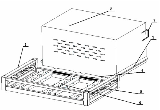
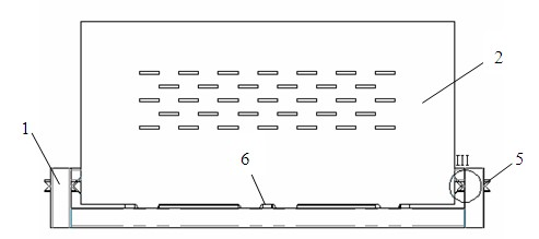
[0031] as attached figure 1 As shown, a trolleybus pull-type quick-change battery box device includes three parts: battery box mounting frame 1, battery box 2 and locking wedge 4, wherein battery box 2 uses energy storage components of electric vehicles such as batteries , supercapacitor, etc. are fixed in the box, and at the same time, a battery management system (BMS), a fan for heat dissipation, and a dust-proof filter required for dust prevention are installed in the box; guide bars are installed at appropriate positions on both sides of the battery box 2 3. The guide bar 3 is a V-shaped angle steel, and the end of the V-shaped angle steel is chamfered at 45°. When the battery box 2 is pushed into the battery box installation frame 1, the chamfer can play a guiding role; pulling the handle 7 can make the battery The box 2 moves in the battery box installation frame 1; and the battery box installation frame 1 is equipped with three rows of casters 6 made of organic polyuret...
Embodiment 2
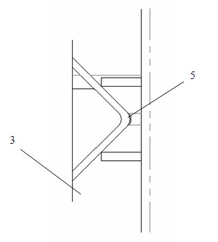
[0035] The basic structure of the second embodiment is the same as that of the first room, except that the section of the guide bar 3 is a full circle or an arc shape, which matches the outer rim of the side roller 5 installed on the side of the battery box mounting frame 1, and the side The outer rim of the roller 5 is inwardly recessed in an arc shape; and in addition to being equipped with a spring below the upper surface of the locking wedge 4, an electromagnet is also provided, and the electromagnet is connected to the upper surface of the locking wedge 4; when the battery When the box 2 is pushed into the battery box installation frame 1, since the bottom of the battery box 2 is engaged with the locking wedge 4, the locking wedge 4 is pressed down during the pushing process, so that the battery box 2 can be easily pushed After the battery box 2 is installed in place, the spring below the locking wedge 4 will jack up the locking wedge 4 to lock and position the battery box...
PUM
 Abstract
Description
Claims
Application Information