Pneumatic roller

A roller and pneumatic technology, applied in the direction of rollers, conveyor objects, transportation and packaging, etc., can solve the problems of heavy weight, motor burnout, and inability to work continuously for a long time, and achieve the effect of long service life

Inactive Publication Date: 2012-01-18
DALIAN JINGYI TECH
View PDF8 Cites 11 Cited by
  • Summary
  • Abstract
  • Description
  • Claims
  • Application Information

AI Technical Summary

Problems solved by technology

However, it also has many limitations, such as the use of special structures in explosive, corrosive, high-temperature and humid working environments; it cannot work continuously for a long time; the motor will burn out under overload, etc.; especially when explosion-proof is required Occasions and when continuous work is required, its structure is large in size, heavy in weight and high in cost

Method used


Image

  • Pneumatic roller
  • Pneumatic roller
  • Pneumatic roller

Examples


Embodiment Construction

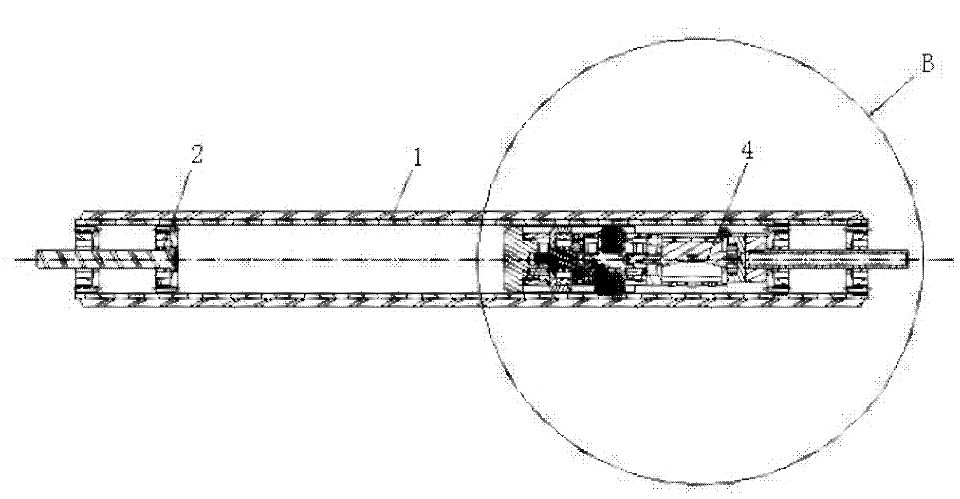
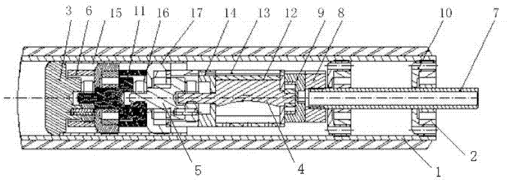
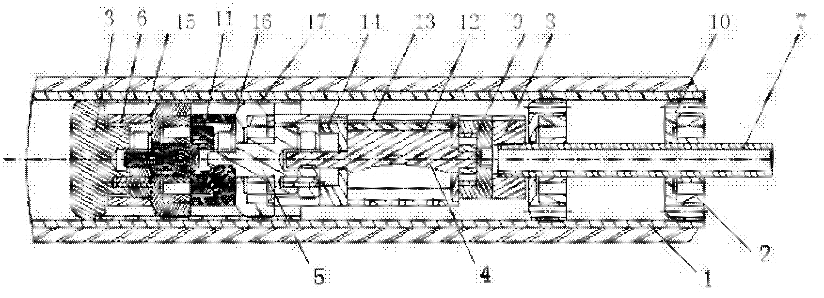
[0010] see figure 1 , 2 , The pneumatic roller includes a roller body 1 and support bearings 2 at both ends of the roller body 1 . There is a pneumatic assembly inside the roller body 1; It is a schematic structural diagram of a typical pneumatic assembly, which uses a double-hole eccentric motor and a three-stage planetary gear reducer.

[0011] Roller body 1 right-hand side bearing 2 middle part has air-intake pipeline 7, and air-intake pipeline 7 li ends are connected with air-intake guide piece 8, air-intake reversing piece 9 and air motor 4, and the bearing sleeve 10 has exhaust hole on it. The air intake guide block 8 guides the high-pressure air entering from the air intake line 7 into the air motor 4 air inlet on the edge, and the air intake reversing block 9 reverses the direction of the air inlet when the roller body 1 is operated in reverse. The air motor 4 includes a rotor 12 , a stator 13 , and a rear end cover 14 . The speed reducer 5 includes a speed reducer...


PUM


Abstract

The invention relates to a driving roller for a conveying mechanism, namely a pneumatic roller. The pneumatic roller comprises a roller body, support bearings at two ends of the roller body and a pneumatic assembly. The pneumatic assembly is composed of an air inflow pipeline, a pneumatic motor and a decelerator. An output wheel of the decelerator is connected with the inner wall of the roller body. The air inflow pipeline is in the middle of the bearing at one end of the roller body. The inner end of the air inflow pipeline is connected with an air inflow guide block, an air inflow reversing block and the pneumatic motor. An exhaust hole is arranged on a bearing sleeve. The pneumatic roller self finally rotates by taking compressed air as a power source through conversion and transfer of a series of force so that the purpose of transporting objects is achieved. The pneumatic roller can be used in special working environments, such as explosive working environments, corrosive working environments, high-temperature working environments, moisture working environments and the like. The pneumatic roller has the characteristics of long service life, less maintenance, continuous working, frequent starting, simple installation, convenience for disassembly and convenience for realizing stepless speed regulation and using clean energy.

Description

technical field [0001] The invention relates to a driving roller for a conveying mechanism, that is, a pneumatic roller (or a pneumatic roller). Background technique [0002] In the prior art, the driving roller of the conveyor is an electric roller, which has been widely used in mining, metallurgy, chemical industry, coal, building materials, electric power, food and transportation and other departments. Its advantages are simple and compact structure, small footprint, and simple and convenient installation. However, it also has many limitations, such as the use of special structures in explosive, corrosive, high-temperature and humid working environments; it cannot work continuously for a long time; the motor will burn out under overload, etc.; especially when explosion-proof is required Occasions and when continuous work is required, its structure is large in size, heavy in quality and high in cost. Contents of the invention [0003] The object of the present inventio...

Claims


Application Information

Patent Timeline
Patent Type & Authority Applications(China)
IPC IPC(8): B65G39/02
Inventor 周爽董凤周瑾
Owner DALIAN JINGYI TECH
Why Eureka
Try Eureka