Sequentially controlled twin steering pump

A sequential control and steering pump technology, which is applied in the direction of pump control, pump, rotary piston type/oscillating piston type pump combination, etc., can solve the problems of increased failure rate, short service life, difficult to realize, etc., and reduce the possibility of carbonization performance, improve work reliability, and reduce the consumption of oil medium

Active Publication Date: 2012-01-18
DALIAN INNOVATION PARTS MANUFACTURING CO LTD
View PDF8 Cites 5 Cited by
  • Summary
  • Abstract
  • Description
  • Claims
  • Application Information

AI Technical Summary

Problems solved by technology

[0003] For heavy trucks and large passenger cars, the steering pump is the core component of the hydraulic power steering system and is also a safety component of the vehicle. The steering pump currently equipped does not have an emergency function, and the general failure rate is high and the service life is short. Greatly affects the safety and reliability of the vehicle steering system
Domestic large-tonnage vehicles run on poor road conditions and are seriously overloaded. Steering pumps at the current technical level are difficult to adapt to the current conditions of use of such vehicles. Even the world's top-level steering pumps still have about 3%-5% of faults rate, when a fault occurs, the power steering function fails, making the vehicle in an extremely dangerous situation
At the current domestic and foreign technical level, for small-displacement steering pumps, high-pressure resistance can be better achieved, but it is difficult to achieve a single pump with large displacement and high-pressure resistance required by heavy trucks. Even if a large displacement is achieved, Its ability to withstand high pressure is poor, its service life is extremely short, and the failure rate will further increase

Method used


Image

  • Sequentially controlled twin steering pump
  • Sequentially controlled twin steering pump
  • Sequentially controlled twin steering pump

Examples


Embodiment Construction

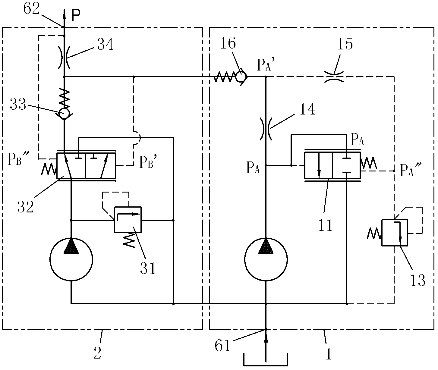
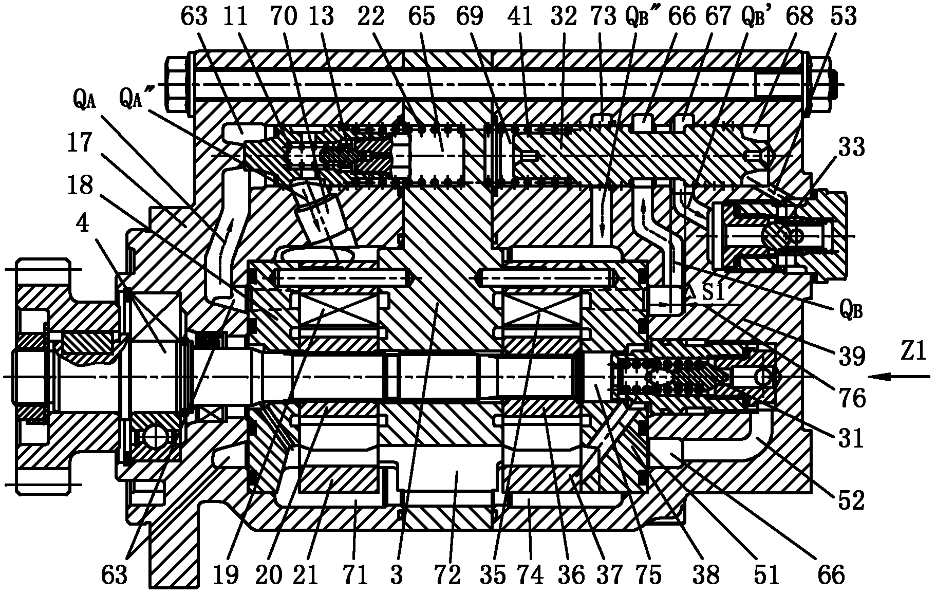
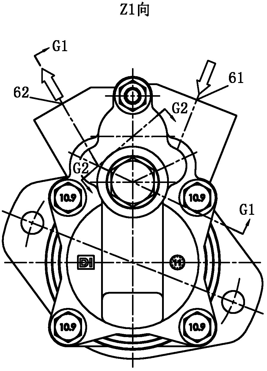
[0036] Below in conjunction with accompanying drawing, the present invention is described in further detail: as Figure 1-12 As shown, a sequence control dual steering pump includes a main pump 1, an auxiliary pump 2, an intermediate body 3 and a pump shaft 4, and the main pump 1 includes a flow control valve I 11, a safety valve I 13, a flow control damping Hole I 14, pressure control damping hole 15, one-way valve I 16, pump body 17, pressure side plate I 18, blade I 19, rotor I 20, stator I 21 and flow control valve spring 22, the auxiliary pump 2 Including safety valve II 31, reversing valve 32, check valve II 33, flow control orifice II 34, vane II 35, rotor II 36, stator II 37, pressure side plate II 38, pump cover I 39 and reversing valve spring 41;

[0037] The annular oil suction chamber 71 of the main pump communicates with the oil inlet 61, and communicates with the annular oil suction chamber 74 of the auxiliary pump through the intermediate oil suction window 72,...


PUM


Abstract

The invention discloses a sequentially controlled twin steering pump, which comprises a main pump, an auxiliary pump, an intermediate and a pump shaft. The main pump includes a flow control valve I, a safety valve I, a flow control damping hole I, a pressure control damping hole, a check valve I, a pump body, a pressure side plate I, a blade I, a rotor I, a stator I, and a flow control valve spring. The auxiliary pump consists of a safety valve II, a reversing valve, a check valve II, a flow control damping hole II, a blade II, a rotor II, a stator II, a pressure side plate II, a pump cover I, and a reversing valve spring. An annular oil suction chamber of the main pump is communicated with an oil inlet and is also communicated with an annular oil suction chamber of the auxiliary pump through an intermediate oil suction window, so that the oil inlet can deliver an oil medium simultaneously to the main pump and the auxiliary pump. The pump of the invention improves steering security, prolongs service life, reduces energy consumption, enhances reliability and lowers steering oil medium consumption. In the pump of the invention, even if the main pump breaks down, the auxiliary pump can substitute automatically, and realizes the function of emergency oil supply.

Description

technical field [0001] The invention relates to a vane type automobile steering oil pump, in particular to a dual steering pump capable of sequential switching control. Background technique [0002] In response to the requirements of FAW Technology Center, Dongfeng Motor Technology Center, Jinan Heavy Duty Truck Technology Center, Beiben Technology Center, and Shaanxi Automobile Technology Center, the application concept of the steering pump equipped with its heavy trucks was redefined, and the steering pump was required to be provided in addition to the normal supply. In addition to steering hydraulic oil, it can also play the role of emergency oil supply. At the same time, further improvements and technical upgrades are required in terms of geometric displacement, pressure resistance, temperature rise reduction, and especially power consumption. [0003] For heavy trucks and large passenger cars, the steering pump is the core component of the hydraulic power steering syste...

Claims


Application Information

Patent Timeline
Patent Type & Authority Applications(China)
IPC IPC(8): F04C11/00F04C14/00
Inventor 侯训波王建宇孙树奎寇西征常涛王旭光巴根屈英贤罗强国
Owner DALIAN INNOVATION PARTS MANUFACTURING CO LTD
Why Eureka
Try Eureka