
Power switching tube driving circuit applied to electronic safety device

A technology of a power switch tube and a driving circuit, which is applied in the electronic field, can solve the problems of high cost, unfavorable design and production, complicated driving circuit design, etc., and achieves the effects of reliable performance, simple structure and easy control.

Inactive Publication Date: 2012-01-18
WEIDMULLER INTERFACE SHANGHAI
View PDF3 Cites 6 Cited by
  • Summary
  • Abstract
  • Description
  • Claims
  • Application Information

AI Technical Summary

Problems solved by technology

It is a reasonable choice to choose P-channel power switch tube at this time, but the cost of P-channel power switch tube is often high, and there are few high-current power switch tubes, which is extremely unfavorable to design and production. The problem with the power switch tube is that once it is driven at the high end, there must be a driving voltage greater than the input voltage between the gate and the source (all referenced to the common ground) to become reliable, and the design of the driving circuit also complicated

Method used


Image

  • Power switching tube driving circuit applied to electronic safety device
  • Power switching tube driving circuit applied to electronic safety device

Examples


Embodiment

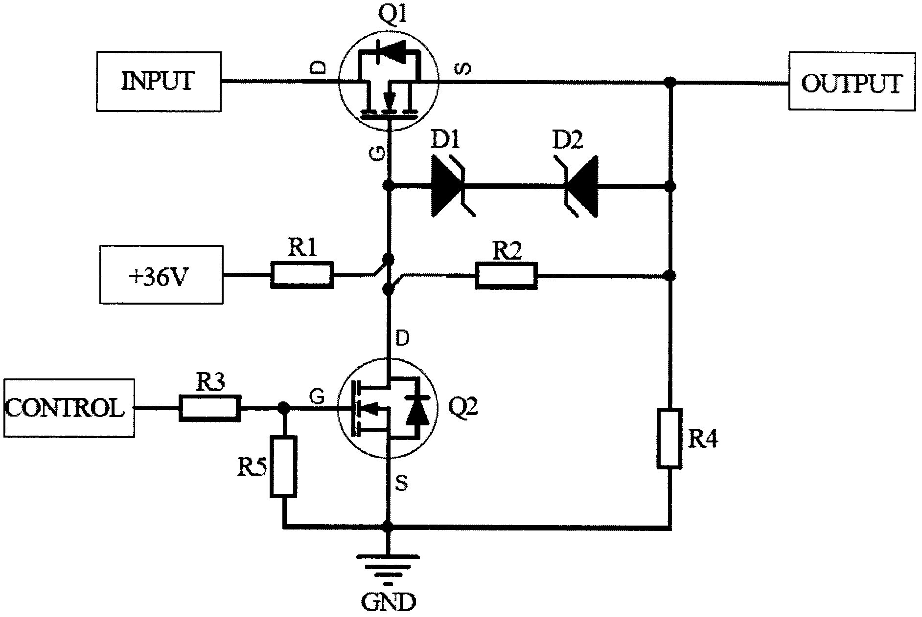
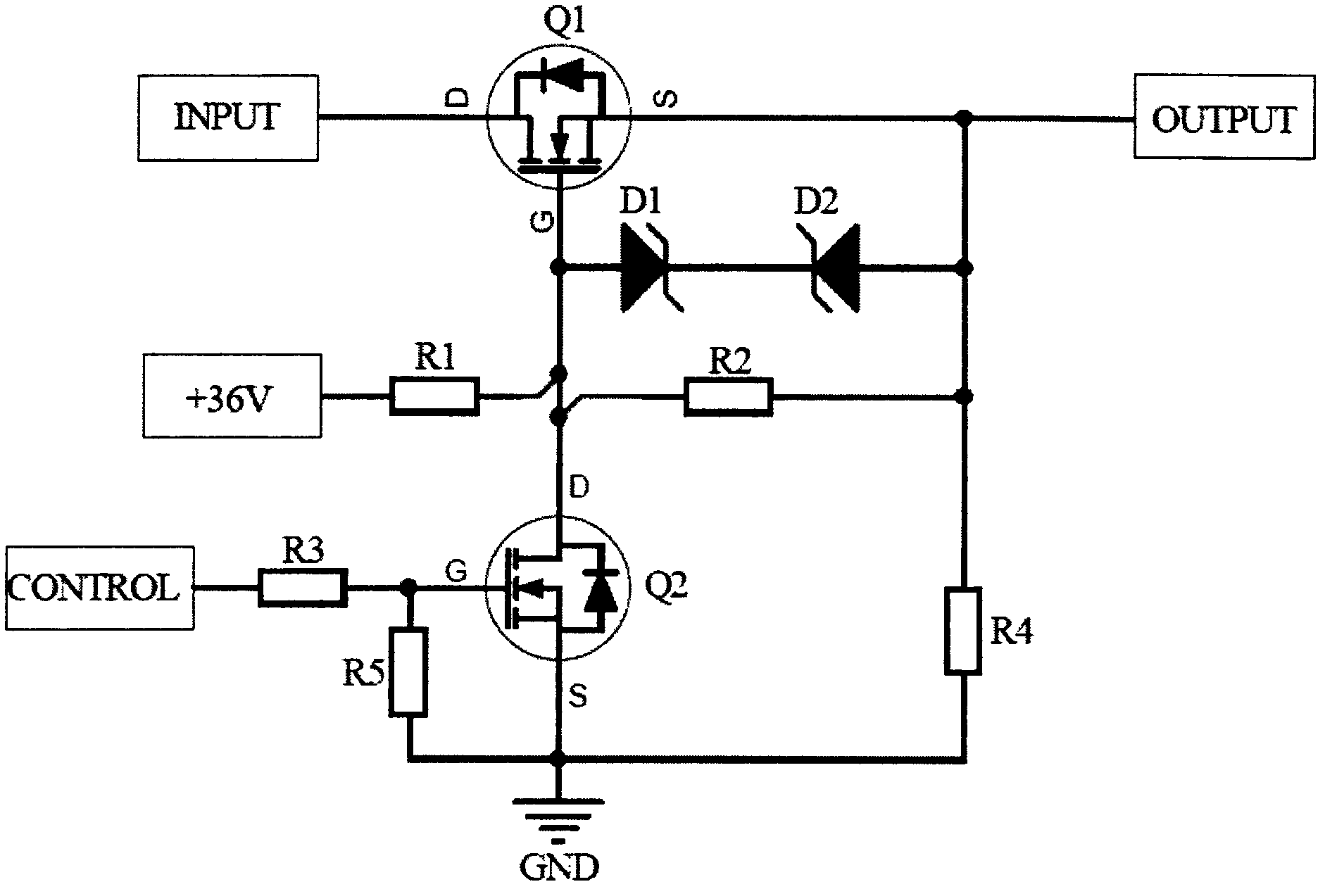
[0015] Example: such as figure 1 As shown, the present invention provides a specific embodiment of a power switch tube driving circuit applied in an electronic insurance device. It includes a power input terminal (INPUT), a power output terminal (OUTPUT), a first power switch tube Q1 whose drain is connected to the positive pole of the power input terminal, and a second power switch tube Q1 whose drain is connected to the gate of the first power switch tube Q1. The switch tube Q2, the auxiliary power supply connected to the gate of the first power switch tube Q1 through the first access resistor R1, and the protection signal (CONTROL) connected to the gate of the second power switch tube Q2 through the second access resistor R3 ), wherein the gate of the first power switching tube Q1 is connected to the positive terminal of the first voltage regulator tube D1 and one end of the first voltage dividing resistor R2 at the same time, and the negative terminal of the first voltage ...


PUM


Abstract

The invention discloses a power switching tube driving circuit applied to an electronic safety device. The circuit comprises a power supply input end, a power supply output end, a first power switching tube, a second power switching tube, an auxiliary power supply and a protection signal, wherein the drain electrode of the first power switching tube is connected with the anode of the power supply input end; the drain electrode of the second power switching tube is connected with the grid electrode of the first power switching tube; the auxiliary power supply is connected to the grid electrode of the first power switching tube by first access resistance; and the protection signal is connected with the grid electrode of the first power switching tube by second access resistance. The power switching tube driving circuit has the advantages of simple structure and reliable performance, is convenient to design, is convenient to control, is a N-channel power switching tube with wider variety and is an ideal circuit for high-end driving.

Description

technical field [0001] The invention belongs to the field of electronic technology, in particular to a power switch tube driving circuit applied in an electronic insurance device. Background technique [0002] In industrial control systems, the requirements for protection circuits are getting higher and higher, especially for fuses. In the field of industrial control, fuses can be divided into two types: recoverable after protection and non-recoverable after protection. The fuse that can be restored after protection has been widely used because of cost savings, reliable performance, and convenient maintenance in the later period. [0003] With the rapid development of science and technology, the fuse can be restored after protection is required in the field of industrial control, which has the characteristics of continuous breaking and recovery, controllable breaking time, breaking of multiple channels with different current levels, communication, and flexible selection of ...

Claims


Application Information

Patent Timeline
Patent Type & Authority Applications(China)
IPC IPC(8): H02M1/08
Inventor 刘兴元陈忠民董建涛顾秀成
Owner WEIDMULLER INTERFACE SHANGHAI
Learn More