Pneumatic safety underground shielding door

A technology for shielded doors and subways, which is applied in the direction of door/window accessories, power control mechanisms, and wing leaf layout. It can solve the problems of high product cost and maintenance cost, complex structure of subway shielded doors, and high failure rate, so as to reduce maintenance cost, increase market competitiveness, and safe and reliable operation

Inactive Publication Date: 2012-01-25
辽宁圣维机电科技股份有限公司
View PDF7 Cites 6 Cited by
  • Summary
  • Abstract
  • Description
  • Claims
  • Application Information

AI Technical Summary

Problems solved by technology

[0005] The purpose of the present invention is to overcome the deficiencies of the existing subway screen door technology, solve the problems of the existing subway screen door complex structure, high failure rate, high product cost and maintenance cost, etc., and provide a pneumatic safety subway screen door, the device Compressed air is used as the power source to realize safe and reliable operation of subway screen doors, simple structure, convenient installation, low product cost and maintenance cost, and then realize energy saving and environmental protection

Method used


Image

  • Pneumatic safety underground shielding door
  • Pneumatic safety underground shielding door
  • Pneumatic safety underground shielding door

Examples


Embodiment 1

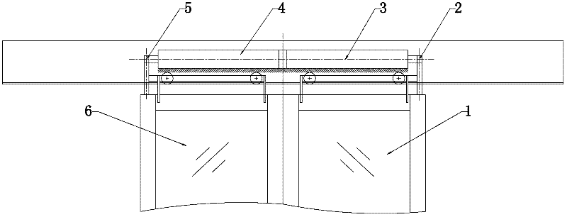
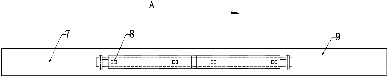
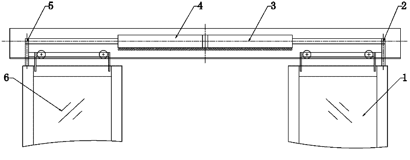
[0028] Embodiment one, pneumatic safety subway screen door, such as figure 1 , figure 2 , image 3 , Figure 4 , Figure 9 , Figure 10 As shown, it includes sliding door leaf one 1, sliding door leaf two 6, pulley 8, slide rail 7, connection plate one 2, connection plate two 5, cylinder one 3, cylinder two 4, pulley frame 10, compressed air storage tank 12, pneumatic Solenoid valve 14, structural frame 9, the top of sliding door leaf one 1 and sliding door leaf two 6 that are arranged side by side respectively adopt pulley rack 10 to be connected with pulley 8, and slide rail 7 is provided with below pulley 8, and pulley 8 can slide rail 7 along The slide rail 7 is set in a reciprocating motion, the sliding door 1 is connected with the piston rod of the cylinder 1 3 through the connecting plate 2 on the right end of the upper edge, and the sliding door 2 6 is connected with the piston rod of the connecting plate 2 5 and the cylinder 2 4 through the left end of the upper ...

Embodiment 2

[0029] Embodiment two, pneumatic safety subway screen door, such as Figure 5 , Image 6 , Figure 7 , Figure 8 , Figure 9 , Figure 10 As shown, it includes sliding door leaf one 1, sliding door leaf two 6, pulley 8, slide rail 7, connection plate one 2, connection plate two 5, cylinder one 3, cylinder two 4, pulley frame 10, compressed air storage tank 12, pneumatic Solenoid valve 14, structural frame 9, the top of sliding door leaf one 1 and sliding door leaf two 6 that are arranged side by side respectively adopt pulley rack 10 to be connected with pulley 8, and slide rail 7 is provided with below pulley 8, and pulley 8 can slide rail 7 along Slide rail 7 sets direction to do reciprocating motion, sliding door leaf one 1 is connected with the piston rod of cylinder one 3 through connecting plate one 2, sliding door leaf two 6 is connected with the piston rod of cylinder two 4 through connecting plate two 5, connecting plate one 2 and Connecting plate 2 5 is respecti...


PUM


Abstract

The invention relates to a pneumatic safety underground shielding door, which comprises a first sliding door leaf, a second sliding door leaf, a pulley, a sliding rail, a first connecting plate, a second connecting plate, a first cylinder, a second cylinder, a pulley frame, a compressed air storage tank, a pneumatic solenoid valve and a structure framework, wherein the pulley is connected to the first sliding door leaf and the second sliding door leaf which are arranged in parallel by using the pulley frame; the sliding rail is arranged below the pulley; the pulley can do reciprocating motion on the sliding rail along the arrangement direction of sliding rail; the first sliding door leaf is connected with a piston rod of the first cylinder through the first connecting plate; the second sliding door leaf is connected with a piston rod of the second cylinder through the second connecting plate; air chambers on the two sides of pistons of the first cylinder and the second cylinder are connected with the compressed air storage tank through the pneumatic solenoid valve. Compared with the prior art, the invention has the advantages that: compressed air is taken as a power source, so the pneumatic safety underground shielding door is safe and reliable in running, simple in structure, convenient to install, low in construction cost and maintenance cost, energy-saving and environment-friendly.

Description

technical field [0001] The invention relates to a traffic track safety device, in particular to a novel pneumatic safety subway screen door. Background technique [0002] With the rapid development of my country's urban infrastructure, urban rail transit is also developing rapidly at the same time, especially in recent years, the construction of subways in large and medium-sized cities in my country has developed rapidly. At present, more than 20 cities in my country are under construction or expanding subway project. According to the requirements of international safety and environmental protection, the subway screen door system must be installed on the subway platform. The function of this system is to form a fully enclosed system for the high-speed subway train and the subway platform. The subway screen door forms a safety barrier for the subway platform. That is to say, it has played a safe protection role for the majority of passengers, and has played an environmental p...

Claims


Application Information

Patent Timeline
Patent Type & Authority Applications(China)
IPC IPC(8): E06B5/10E06B3/46E05D13/00E05F15/06E05F15/20E05F15/70
Inventor 陈洪彦陈熙文
Owner 辽宁圣维机电科技股份有限公司
Why Eureka
Try Eureka