Photometry device

一种光谱、测量值的技术,应用在测光装置领域,能够解决测量值低有效性、无法广泛应用等问题,达到改善测量精度的效果

Inactive Publication Date: 2012-01-25
PANASONIC CORP
View PDF4 Cites 1 Cited by
  • Summary
  • Abstract
  • Description
  • Claims
  • Application Information

AI Technical Summary

Problems solved by technology

[0005] However, since the relationship between the spectral luminous efficiency of mesopic vision and the color temperature of the light source is uncertain, such traditional examples cannot be widely applied due to the low validity of their measured values.

Method used


Image

  • Photometry device
  • Photometry device
  • Photometry device

Examples


no. 1 example

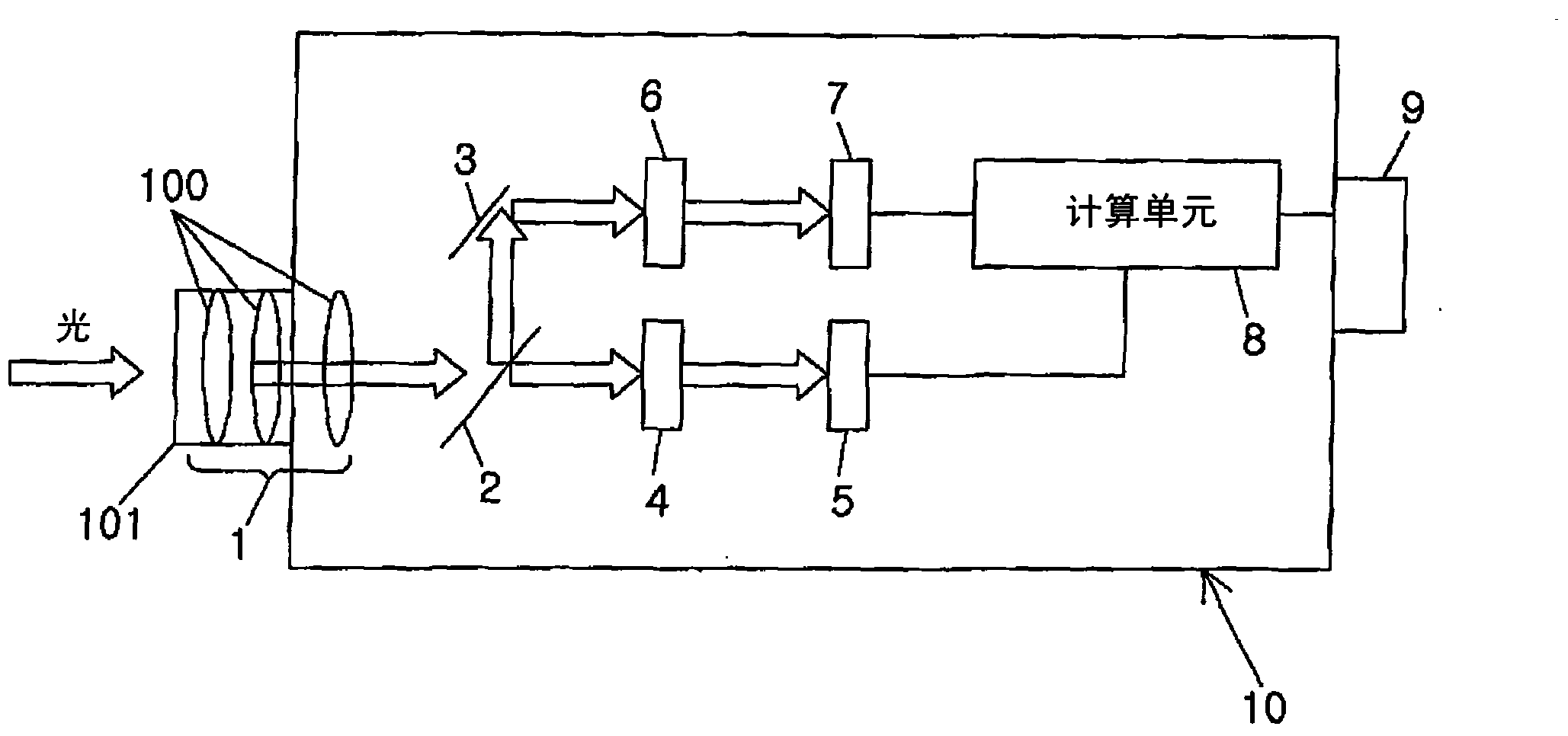
[0016] Such as figure 1 As shown, the photometric device of the current embodiment is provided with an optical component 1, a half mirror 2, a mirror 3, a first filter 4, a first photoelectric converter 5, a second filter 6, a second photoelectric converter 7, computing unit 8, display 9 and housing 10.

[0017] The housing 10 has a box-like shape and is made of synthetic resin or metal. Light is introduced into the housing 10 via a hole opened on the left side of the housing.

[0018] The optical part 1 includes a plurality of convex lenses 100 ; and a cylindrical body 101 supporting the convex lenses 100 and closing a hole of the housing 10 . Therefore, the light introduced through the hole is converged by the convex lens 100 of the optical component 1 .

[0019] The half mirror 2 is provided on the optical path of the optical component 1, and divides the light condensed by the optical component 1 into two parts. On one optical path branched by the half mirror 2, a first...

no. 2 example

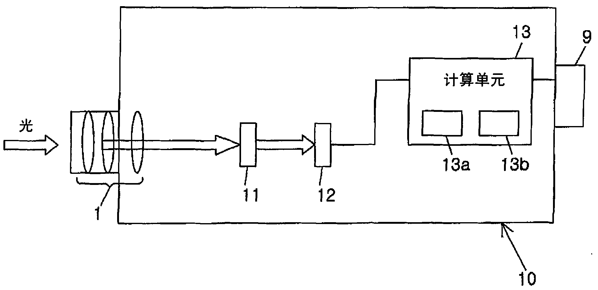
[0028] Such as image 3 As shown, the photometric device of the current embodiment includes: a spectral filter 11 for dispersing incident light; Measuring means 12; and calculating means 13 for calculating mesopic luminance. The same reference numerals are used for components common to the photometry device of the first embodiment, and description thereof will be omitted.

[0029] The spectral filter 11 is configured with a prism, and divides (disperses) incident light into a plurality of wavelength bands by utilizing its different refractive index depending on the wavelength of light. The measuring section 12 has a plurality of photoelectric transducers (not shown) corresponding to each wavelength band of light dispersed by the spectral filter 11; and a plurality of amplifiers (not shown) that amplify the output voltages of the respective photoelectric transducers. out).

[0030] The calculation section 13 mainly includes: an A-D converter (not shown) for quantizing (A-D c...


PUM


Abstract

In a photometry device, photopic vision luminance Lp is measured by a first luminance measuring unit including a first light filter 4 and a first photoelectric converter 5, and scotopic vision luminance Ls is measured by a second luminance measuring unit including a second light filter 6 and a second photoelectric converter 7. A calculation part 8 calculates mesopic vision luminance Lmes based on a measurement value (photopic vision luminance Lp) of the first luminance measuring unit and a ratio of a measurement value (scotopic vision luminance Ls) of the second luminance measuring unit to the measurement value (photopic vision luminance Lp) of the first luminance measuring unit. Consequently, the photometry device can improve measurement accuracy of the brightness (mesopic vision luminance) in mesopic vision.

Description

technical field [0001] The present invention relates to a photometry device for measuring brightness in scotopic and mesopic vision. Background technique [0002] The spectral luminous efficiency of the naked human eye varies in photopic, scotopic, and mesopic vision. In photopic vision, the cones are used to perceive color. In scotopic vision, although color cannot be perceived because there are no cones working, the rods work to improve color sensitivity. In mesovision, an intermediate state between photopic and scotopic vision, both cones and rods work. Here, the spectral luminous efficiency has a peak wavelength of approximately 555 nm in photopic vision. On the other hand, spectral luminous efficiency has a shifted peak wavelength of approximately 507 nm in scotopic vision. Such a phenomenon is known as "Purkinje phenomenon". [0003] As an index of brightness sensed by human eyes, luminance and illuminance are typically employed. However, for conventional luminan...

Claims


Application Information

Patent Timeline
Patent Type & Authority Applications(China)
IPC IPC(8): G01J1/42
CPCA61B3/1225A61B3/1208G01J1/04A61B3/00G01J1/0477G01J1/4228G01J1/1626
Inventor 斋藤孝野口公喜户田直宏槻谷绫子西冈浩二高嶋彰茨薰山添健介久保浩枝唐沢宜典
Owner PANASONIC CORP
Why Eureka
Try Eureka