Method for machining composite components

A composite component, processing station technology, used in manufacturing tools, general control systems, program-controlled robots, etc.

Inactive Publication Date: 2012-01-25
LIEBHERR VERZAHNTECHNIK GMBH
View PDF12 Cites 7 Cited by
  • Summary
  • Abstract
  • Description
  • Claims
  • Application Information

AI Technical Summary

Problems solved by technology

This high-tech construction type provides the outstanding stability and flexibility needed, however, while keeping the flaps thin and light

Method used


Image

  • Method for machining composite components
  • Method for machining composite components
  • Method for machining composite components

Examples


Embodiment Construction

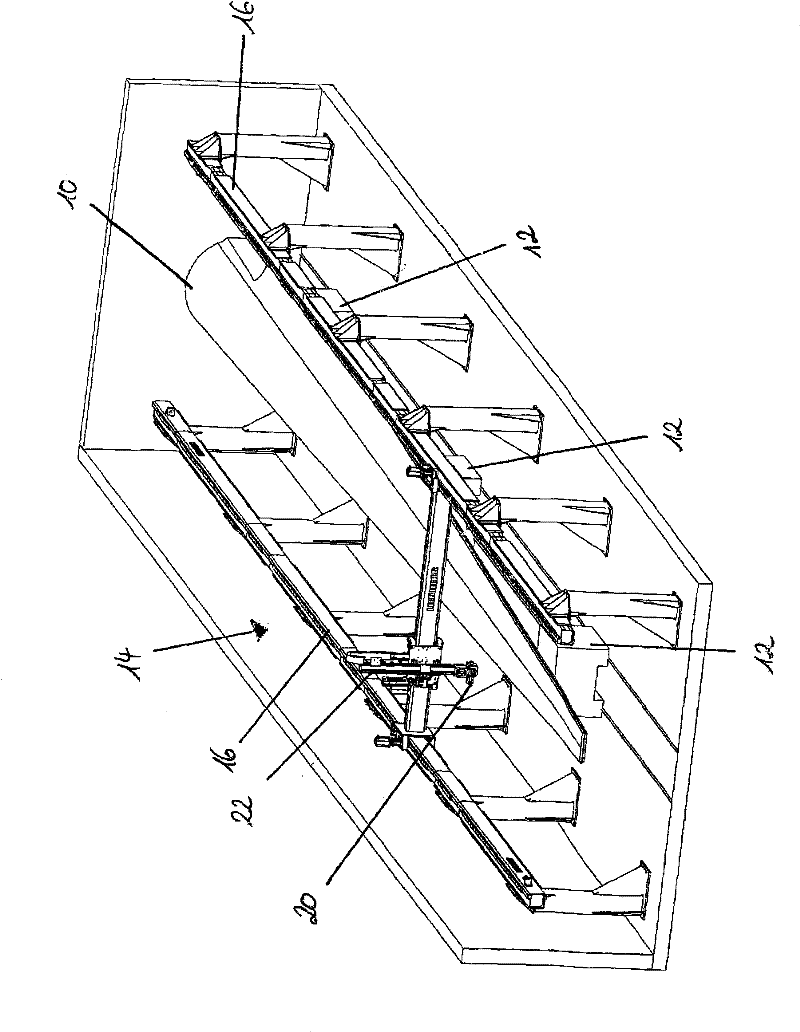
[0029] in figure 1 For example, a rotor blade 10 is shown as a composite component to be processed. In the rotor blade 10 shown here, the rotor blade halves are directly bonded to each other. The resin overflows from the bonding seam in a manner not shown in detail here, so that a redundant part is generated here, which must be removed for further completion. To this end, the rotor blade 10 is fixedly clamped on the multi-part component holder 12. The clamped rotor blade 10 is surrounded by a plane door-shaped frame 14 in the working aisle, in which the door-shaped frame guide devices 16 are respectively arranged sideways. In the plane door frame 14, a processing tool 20 is provided on the lifting shaft 22.

[0030] Through the flat door-shaped frame 14, the processing head 20 with the installed processing tools can move along the composite component to be processed for processing the linear seam area.

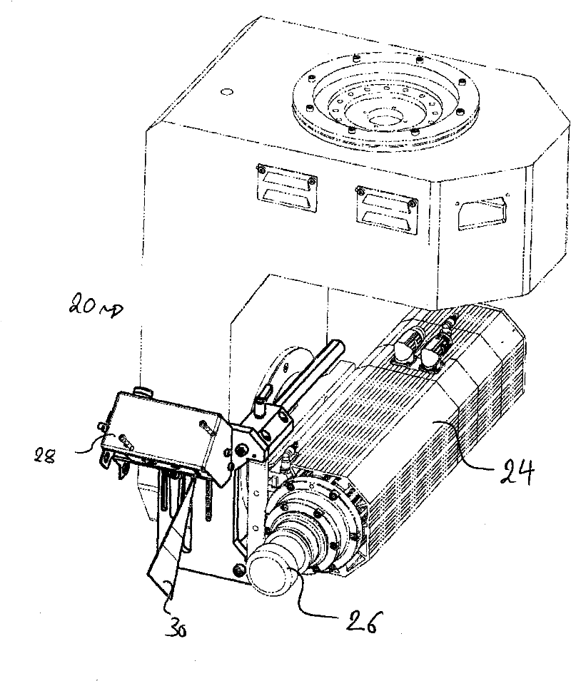
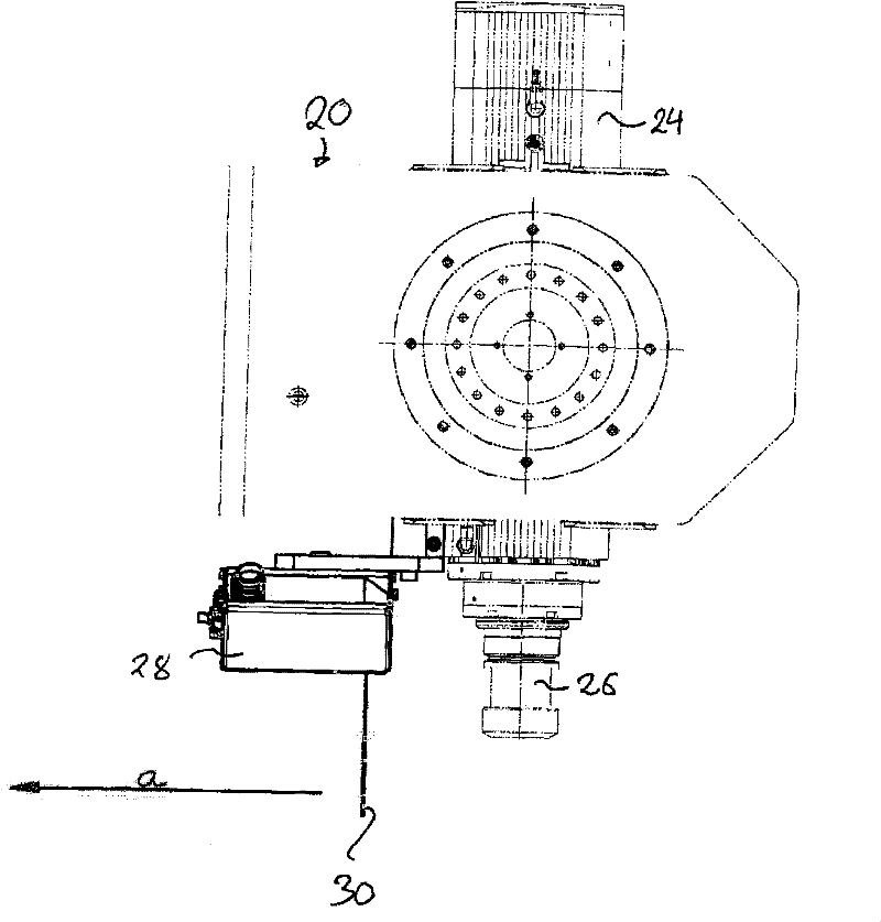
[0031] in figure 2 with 3 The processing head 20 is shown in more detail i...


PUM


Abstract

The present disclosure relates to a method for machining composite components in a CNC controlled machining station. In accordance with the present disclosure, a machining tool is guided along a preset tool edge by means of a measuring system, wherein it simultaneously carries out the machining operation, while the CNC control program to control the machining tool is generated in accordance with the measured result. The present disclosure furthermore relates to an apparatus for the carrying out of the method.

Description

Technical field [0001] The invention relates to a method for processing large composite components in a computer numerically controlled processing station. Background technique [0002] Large composite components of this type as the object of the present invention are, for example, rotor blades for wind power plants. The rotor blades are mostly manufactured manually in high-cost production steps. The largest and most modern fins consist of bonded glass fiber and carbon fiber mats in which epoxy resin is injected under vacuum. This type of high-tech structure provides the required outstanding stability and flexibility, but at the same time keeps the flap thin and light. [0003] In principle, the method for producing rotor blades consists of the following steps: [0004] First, the tool mold consisting of two heatable half shells is loaded with parting agent. The tool mold half shell is laid with a glass fiber mat and another reinforcing material. [0005] Then a special hose is in...

Claims


Application Information

Patent Timeline
Patent Type & Authority Applications(China)
IPC IPC(8): G05B19/19
CPCG05B2219/37558G05B2219/40057B25J9/1684G05B2219/39243G05B2219/37452G05B19/401G05B2219/39235G05B19/4099G05B2219/45151G05B2219/36248G05B2219/49238
Inventor 阿洛伊斯·蒙特托马斯·马特恩威廉·肯纳克内希特
Owner LIEBHERR VERZAHNTECHNIK GMBH
Why Eureka
Try Eureka