Water-cooling wall

A technology of water-cooled wall and water-cooled tube, applied in the field of nuclear safety, to achieve the effect of enhancing inherent safety, reducing the impact of system safety, and reducing equipment

Active Publication Date: 2012-01-25
CHINERGY CO LTD
View PDF4 Cites 6 Cited by
  • Summary
  • Abstract
  • Description
  • Claims
  • Application Information

AI Technical Summary

Problems solved by technology

[0005] The technical problem to be solved by the present invention is: how to impro

Method used


Image

  • Water-cooling wall
  • Water-cooling wall
  • Water-cooling wall

Examples


Embodiment Construction

[0024] The specific implementation manners of the present invention will be further described in detail below in conjunction with the accompanying drawings and embodiments. The following examples are used to illustrate the present invention, but are not intended to limit the scope of the present invention.

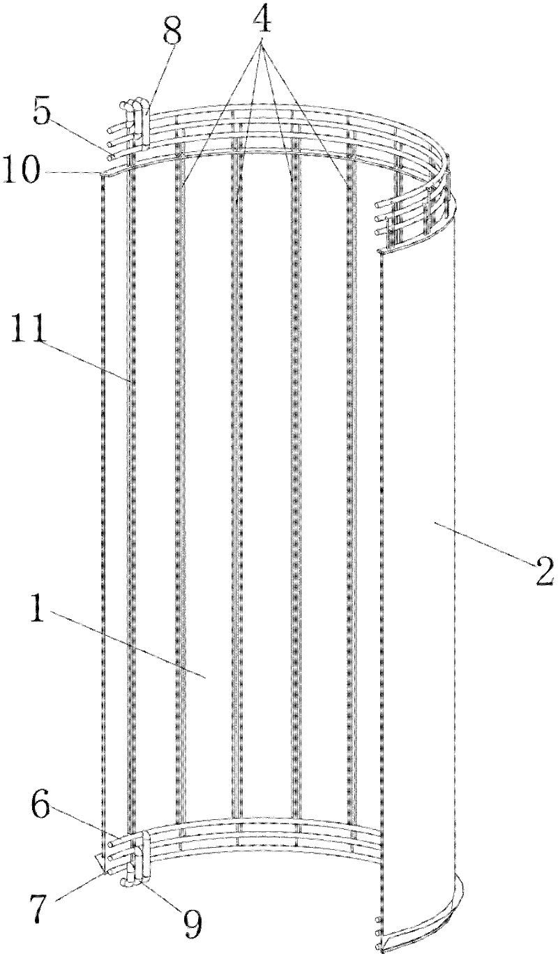
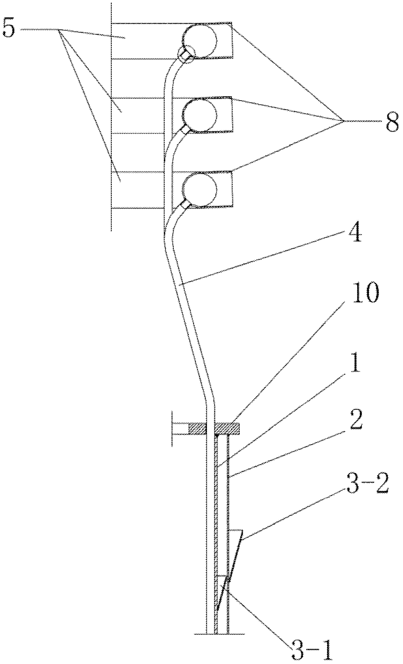
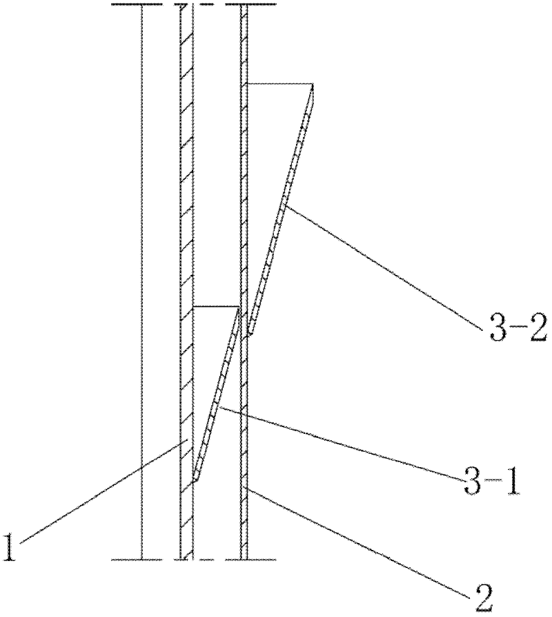
[0025] figure 1 is a three-dimensional cross-sectional view of a water wall according to an embodiment of the present invention; figure 2 yes figure 1 An enlarged view of the top end of the cylindrical side wall of the water wall shown; image 3 yes figure 1 An enlarged view of the middle part of the cylindrical side wall of the water wall shown; Figure 4 for figure 1 An enlarged view of the lower end of the cylindrical sidewall of the water wall shown. refer to Figure 1~4 , the water-cooled wall of this embodiment includes: a cylindrical side wall 1 and a water-cooled pipe 4 arranged on the cylindrical side wall 1, the upper end of the water-cooled pipe 4 commun...


PUM


Abstract

The invention discloses a water-cooling wall, which relates to the technical field of nuclear safety. The water-cooling wall comprises a barrel-shaped side wall and a water-cooling tube arranged on the barrel-shaped side wall, wherein the upper end of the barrel-shaped side wall is communicated with an outlet header; the lower end of the water-cooling tube is communicated with an inlet header; the outlet header and an outlet main tube are communicated; and the inlet header and an inlet main tube are communicated. based on a non-dynamic safe concept, the water-cooling wall performs heat exchange only in natural circulation modes, such as thermal radiation, heat conduction, heat convection and the like, and the effect of an active part, such as a water pump and the like, is not required. A simplified system, less equipment and the mature technology are adopted so as to reduce influence of uncertain factors on system safety as much as possible and increase the inherent safety of a high temperature gas cooled reactor.

Description

technical field [0001] The invention relates to the technical field of nuclear safety, in particular to a water cooling wall. Background technique [0002] After the nuclear reactor is shut down, due to the remaining fission in the core and the decay of fission products, the residual heat generated is still considerable for a long period of time, and it needs to be carried out to the final heat through a specially designed safety-level waste heat removal system. trap. Otherwise, the heat accumulation and temperature rise in the reactor may lead to damage or even melting of fuel elements, thus causing serious nuclear accidents in which radioactivity is released. Therefore, the waste heat removal system is one of the important safety systems of nuclear reactors. [0003] In early commercial high-temperature gas-cooled reactor demonstration power plants, such as THTR-300 in Germany, the main heat exchanger of the waste heat removal system used forced circulation to cool the c...

Claims


Application Information

Patent Timeline
IPC IPC(8): G21C15/18
CPCY02E30/33Y02E30/30
Inventor 张丽何树延李晓伟吴莘馨吴宗鑫张作义
Owner CHINERGY CO LTD
Why Eureka
Try Eureka