Method for anti-surge circuit for electromagnetic induction heating appliance

An electromagnetic induction heating and anti-surge technology, which is applied in induction heating, emergency protection circuit devices for limiting overcurrent/overvoltage, electrical components, etc. Damage and other issues

Inactive Publication Date: 2015-02-25
SHENZHEN H&T INTELLIGENT CONTROL
View PDF4 Cites 0 Cited by
  • Summary
  • Abstract
  • Description
  • Claims
  • Application Information

AI Technical Summary

Problems solved by technology

like figure 1 As shown, in the prior art, when the power input of the induction cooker generates surge interference, the interference signal is amplified by the secondary of the current transformer T1 and rectified by D1, D2, D3, D4, and a disturbance signal is generated at the positive terminals of D1 and D3 , the disturbance signal causes the potential change of pin 7 of U1 through resistors R5, R6, and R2, and a low-level output signal is generated at pin 1 of the output terminal of U1 comparator, and the signal is sent to the single-chip microcomputer (microcontroller) to generate an interrupt. The other way is directly sent to the switching device ( figure 1 The middle is IGBT) driving circuit, after passing through the driving circuit, a low level is generated on the gate of the IGBT, so that the IGBT is cut off and the IGBT is protected. The disadvantage of this circuit is that the low level time of the surge detection signal output is very short, and the hardware turns off the IGBT. The time is very short, it depends on the software to turn off the IGBT drive signal for a long time, when there is a continuous surge pulse interference signal in the power grid, because the reaction speed of the single chip microcomputer is not fast enough, sometimes it will cause damage to the above switching devices

Method used


Image

  • Method for anti-surge circuit for electromagnetic induction heating appliance
  • Method for anti-surge circuit for electromagnetic induction heating appliance
  • Method for anti-surge circuit for electromagnetic induction heating appliance

Examples


Embodiment Construction

[0024] Embodiments of the present invention will be further described below in conjunction with the accompanying drawings.

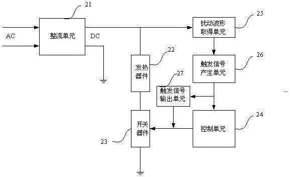
[0025] Such as figure 2 As shown, in the embodiment of the anti-surge circuit for the electromagnetic induction heating appliance and the heating appliance thereof in the present invention, the electromagnetic induction heating appliance is an electromagnetic oven, and the electromagnetic oven circuit includes: a heating device 22, a circuit for converting the AC voltage into a DC voltage The rectifying unit 21, the switching device 23 that controls the above-mentioned DC voltage to pass through the heating device 22, and the control unit 24 that controls the switching device 23 to be turned on or off. Generally speaking, the control unit 24 is a microcontroller plus an oscillation circuit and a driving circuit. During its operation, the rectifying unit 21 converts the AC voltage on the AC grid into a DC voltage at figure 2 The two ends of the marked ...


PUM


Abstract

The invention relates to an anti-surge circuit for an electromagnetic induction heating appliance. The anti-surge circuit comprises a disturbance waveform obtaining unit, a triggering signal forming unit and a triggering signal outputting unit; the duration of a triggering signal output by the triggering signal forming unit is more than that of a disturbance waveform, wherein the input end of the disturbance waveform obtaining unit is connected to a direct-current voltage output end of a rectification unit; the output end of the disturbance waveform obtaining unit is connected to the input end of the triggering signal forming unit; the output end of the triggering signal forming unit is connected to the input end of the triggering signal outputting unit; the output end of the triggering signal outputting unit is connected with a control end of a switch device; and the output end of the triggering signal forming unit is also connected with an interruption input end of a control unit. By utilizing the anti-surge circuit for the electromagnetic induction heating appliance, the heating appliance and the method disclosed by the invention, the switch device cannot be damaged.

Description

technical field [0001] The present invention relates to household appliances, more specifically, to a surge prevention method for electromagnetic induction heating appliances. Background technique [0002] Surge disturbances widely exist in reality, such as lightning, starting and stopping of motors, etc., will generate surge voltage on the AC power supply or AC grid. When the surge voltage enters other electrical appliances, it will cause a sharp change in its voltage, which will affect the normal operation of other electrical appliances, and even damage the components in the electrical appliances in severe cases. People usually take steps to avoid its interference. Such as figure 1 As shown, in the prior art, when the power input of the induction cooker generates surge interference, the interference signal is amplified by the secondary of the current transformer T1 and rectified by D1, D2, D3, D4, and a disturbance signal is generated at the positive terminals of D1 and ...

Claims


Application Information

Patent Timeline
Patent Type & Authority Patents(China)
IPC IPC(8): H02H9/04H05B6/02
Inventor 伍炎军胡璐袁天龙邱迅捷邓维成
Owner SHENZHEN H&T INTELLIGENT CONTROL
Why Eureka
Try Eureka