Dynamic power flow control device for multi-frequency modulation based controllable transformer and control method thereof

A dynamic power flow and control device technology, applied in the field of flexible power transmission, can solve the problems of large loss of FACTS devices, complex control structure, system stability problems, application limitations, etc.

Active Publication Date: 2012-01-25
STATE GRID CORP OF CHINA +1
View PDF3 Cites 5 Cited by
  • Summary
  • Abstract
  • Description
  • Claims
  • Application Information

AI Technical Summary

Problems solved by technology

[0008] Although the current FACTS technology has many of the above advantages, it also has great limitations: the cost of the FACTS device is high, and it is difficult to popularize and apply; there are adverse effects between FACTS and power equipment and other controllers; the loss of the FACTS device itself is large ; The complex control structure of the FACTS device and the requirements for corresponding auxiliary equipment such as communication facilities put forward stricter requirements for the operation and control of the power grid; additional problems caused by device failure; system stability problems caused by series connection etc. make its application in the power grid very limited

Method used


Image

  • Dynamic power flow control device for multi-frequency modulation based controllable transformer and control method thereof
  • Dynamic power flow control device for multi-frequency modulation based controllable transformer and control method thereof
  • Dynamic power flow control device for multi-frequency modulation based controllable transformer and control method thereof

Examples


Embodiment Construction

[0087] The present invention will be further described below in conjunction with the embodiments and accompanying drawings, but the protection scope of the present invention should not be limited thereby.

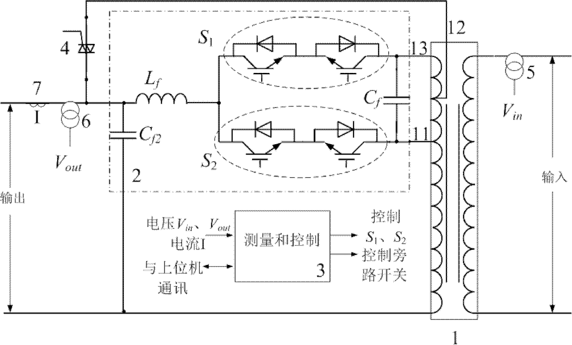
[0088] see first figure 1 , figure 1 It is a structural schematic diagram of a dynamic power flow control device based on a multi-frequency modulation controllable transformer of the present invention. It can be seen from the figure that a controllable transformer-based dynamic power flow control device based on multi-frequency modulation includes: controllable transformer 1, power unit 2, measurement and control module 3, bypass switch 4, input voltage transformer 5, output Potential transformer 6 and output current transformer 7 form:

[0089] The secondary side of the controllable transformer 1 includes a main connector 12 and a positive tap 13 and a negative tap 11;

[0090] The power unit 2 is composed of the first group of power tubes S 1 , the second group of pow...


PUM


Abstract

The invention relates to a dynamic power flow control device for a multi-frequency modulation based controllable transformer. The dynamic power flow control device is composed of a controllable transformer, a power unit, a measuring and controlling module, a bypass switch, an input voltage transformer, an output voltage transformer and an output current transformer. A dynamic power flow control method comprises the following steps of: utilizing a quick turn-on/off electronic power switch to control the turn-on/off of a tap joint at an output side (secondary edge) of the controllable transformer; in a pulse width modulation signal, adopting a direct current signal to inject a multi-frequency (two or more frequencies) signal; and changing a phase and amplitude of an output voltage of the controllable transformer by changing the amplitude of the direct current signal as well as the amplitude and initial phase of the multi-frequency signal in the pulse width modulation signal, thereby realizing the adjustment for active power and reactive power. The turn-on of the tap joint of the controllable transformer is controlled and a harmonic wave of the multi-frequency modulation is reduced, thereby realizing the adjustment and control for the dynamic power flow of a power grid. The dynamic power flow control device and method have the characteristics of small harmonic wave, low cost and high control reliability.

Description

technical field [0001] The invention relates to the technical field of flexible power transmission, in particular to a dynamic power flow control device and a control method of a controllable transformer based on multi-frequency modulation. Background technique [0002] With the interconnection of large-scale power systems and the use of various new equipment, while making power generation and transmission more economical and efficient, the scale and complexity of the power system have also increased, and the possibility of the power grid operating on the edge of the stability limit has also greatly increased. . Therefore, the flexibility of power grid operation, controllability of power flow and stability of power grid have become more and more urgent problems to be solved. In addition, due to the constraints of environmental protection, land use and other factors, it is urgent to use the existing transmission network to transmit more power in order to minimize operating c...

Claims


Application Information

Patent Timeline
Patent Type & Authority Applications(China)
IPC IPC(8): H02J3/00H02J3/18H02J3/01
CPCY02E40/30Y02E40/40
Inventor 江秀臣李国杰盛戈皞冯琳
Owner STATE GRID CORP OF CHINA
Why Eureka
Try Eureka