Dispersion compensation method for broadband light source

A broadband light source and dispersion compensation technology, applied in electromagnetic wave transmission systems, electrical components, transmission systems, etc., can solve problems such as noise and errors, inability to realize ultra-broadband optical signals, complex implementation devices, etc., and achieve high test accuracy and real-time performance Good, real-time good effect

Active Publication Date: 2012-01-25
TIANJIN UNIV
View PDF3 Cites 27 Cited by
  • Summary
  • Abstract
  • Description
  • Claims
  • Application Information

AI Technical Summary

Problems solved by technology

The above dispersion compensation methods mostly use dispersion compensating fiber or electrical and optical phase modulation compensation methods. These methods can only compensate for optical fibers with fixed dispersion values, or due to...

Method used


Image

  • Dispersion compensation method for broadband light source
  • Dispersion compensation method for broadband light source
  • Dispersion compensation method for broadband light source

Examples


Embodiment approach example 2

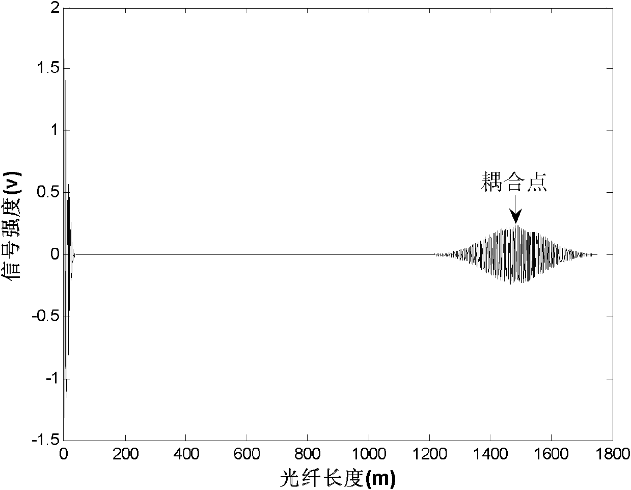
[0036] The 1310nm polarization-maintaining fiber used in the experiment generally has a very small birefringence dispersion coefficient, but when the fiber length is long, the birefringence dispersion of the fiber will make the interference light signal broaden more seriously. Therefore, in the experiment, a 1000m polarization-maintaining optical fiber was connected to the system. As described in Example 1 of the embodiment, it can be measured that there will be a large coupling point at 1000m. The envelope of coupled mode interference data is used for dispersion compensation, and the results before and after compensation are as follows Figure 5 As shown, it can be seen that after compensation, the width of the envelope of the interference data between the excited mode and the coupled mode at 1 / e is reduced from 373.07um to 39.93um.

Embodiment approach example 3

[0038] In order to further illustrate the importance of dispersion compensation when using a broadband light source as the light source of the test system, a 400m polarization-maintaining fiber is connected to the system, and an external force is applied at a distance of about 10cm from the joint between the 400m fiber and the polarizer. Case 1 and the principle of polarization coupling test, there will be a coupling point at 399.9m and 400m respectively, due to the long transmission distance, the envelopes of the interference data of the excited mode and the coupled mode at the two coupling points will widen and overlap to distinguish Not open, but the interference data envelope at the two coupling points after dispersion compensation is about 4.7 times narrower than that before compensation, so the two close coupling points can be easily distinguished. The results before and after compensation are as follows Figure 6 shown.


PUM


Abstract

The invention discloses a dispersion compensation method for a broadband light source. A polarization-preserving fiber polarization coupling testing system based on a Michelson interferometer is formed by the broadband light source, and the Michelson interferometer compensates the optical path difference between an excitation mode and a coupling mode in the polarization-preserving fiber, and a detector acquires an interference signal; specifically, the method comprises the following steps of: intercepting the initial data acquired by the detector through a window function, and taking out the interference data Imain between the excitation modes and the interference data Icoupling between the excitation mode and the coupling mode; respectively executing Hilbert transformation and Gaussian fitting on the Imain and the Icoupling, obtaining envelopes (I)main and (I)coupling of the interference signal, getting a birefringence dispersion coefficient Delta D according to a ratio Eta of the width of the (I)main to the width of the (I)coupling at a 1/e part, obtaining a phase factor needed for the dispersion compensation, and then multiplying the phase factor by a nonlinear frequency spectrum function with dispersion information to eliminate nonlinear phase items causing the widening of the interference signal envelopes; and finally, obtaining the dispersion compensated interference signal Icomp by executing Fourier inversion on the obtained linear frequency spectrum function.

Description

technical field [0001] The invention relates to a polarization-maintaining optical fiber polarization coupling test technology, in particular to a dynamic dispersion compensation method for a polarization-maintaining optical fiber polarization coupling test system built by a broadband light source, and belongs to the technical field of high-precision measurement. Background technique [0002] A broadband light source refers to a low-coherence light source with a certain spectral width and a short coherence length. Because the light source has a wide spectral width, the interference system built by it is often called a white light interference system. In commonly used photoelectric interferometry systems, the most commonly used light sources are various single-mode or narrow-band high-coherence lasers. Under precise measurement conditions, the system can obtain nanometer-level measurement accuracy, but the single-value dynamic range of this type of measurement system is gener...

Claims


Application Information

Patent Timeline
IPC IPC(8): H04B10/18H04B10/2525
Inventor 张红霞任亚光贾大功刘铁根张以谟
Owner TIANJIN UNIV
Why Eureka
Try Eureka