
Catalyst rapid reducing method

A catalyst and reduction furnace technology, applied in chemical instruments and methods, catalyst activation/preparation, physical/chemical process catalysts, etc., can solve the problems of long catalyst reduction time and hydrogen consumption, and achieve hydrogen saving, time saving, reduction short time effect

Active Publication Date: 2012-02-01
CHINA PETROLEUM & CHEM CORP +1
View PDF1 Cites 0 Cited by
  • Summary
  • Abstract
  • Description
  • Claims
  • Application Information

AI Technical Summary

Problems solved by technology

[0004] Aiming at the problems of long catalyst reduction time and hydrogen consumption common in current industrial production, the inventor analyzed the water vapor concentration in the tail gas of the reduction furnace on-line in real time on the basis of the existing operation, and analyzed it using the reduction control program of the control system. Data to adjust the hydrogen flow rate and heating rate parameters of the reduction furnace

Method used


Image

  • Catalyst rapid reducing method
  • Catalyst rapid reducing method

Examples


Embodiment 1

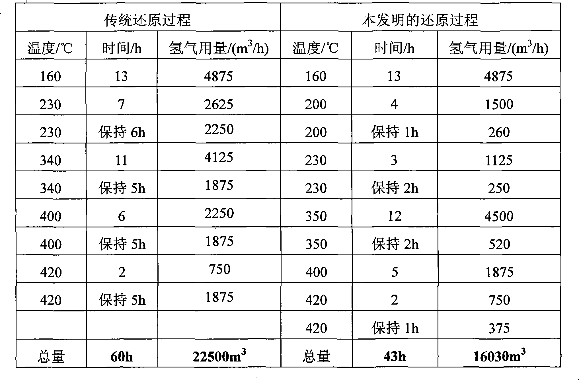
[0025] The method of the present invention is applied to the nickel-based catalyst reduction process. The loading amount of nickel-based catalyst is 1.0m 3 , the heating rate is 10℃ / h, and the nitrogen flow rate is 125m 3 / h, the initial hydrogen flow rate is 375m 3 / h, the specific steps of the traditional reduction method and the method of the present invention are shown in Table 1. The reduced catalyst is at 152°C and the volume space velocity of acetone is 0.5h -1 , Acetone: hydrogen: the mol ratio of ammonia is 1: 3: 3, and the catalyst consumption is the evaluation on the isopropylamine evaluation device of 50ml, and the evaluation results are shown in Table 2.

[0026] The specific operation of the method of the present invention is as follows: the initial heating rate of the reduction furnace is set to be 10°C / h, and the nitrogen flow rate is 125m 3 / h, the initial hydrogen flow rate is 375m 3 / h, turn on the reduction control program to increase the temperature, ...


PUM


Abstract

The invention relates to a catalyst rapid reducing method. According to the method, with a reducing furnace reduction controlling program, a hydrogen flow and a heating rate are automatically maintained and regulated according to on-line monitored values and variation trends of water vapor content and hot spot temperature of reduction tail gas. With the method, controlling over catalyst reductionfurnace automatic reduction can be realized; an entire reduction process can be monitored; an entire catalyst reduction time can be reduced; and a hydrogen usage amount can be reduced. Therefore, theprocessing period and the processing cost of the catalyst are greatly reduced.

Description

technical field [0001] The present invention relates to a catalyst reduction method, more specifically, to a method for rapid catalyst reduction. Background technique [0002] The rapid development of modern chemical industry, especially coal and petrochemical industry, thousands of chemical raw materials and commodity production are closely related to the development of industrial catalysts. The existence of catalyst not only promotes technological innovation in industrial production, but also provides a broad space for human production activities. Most of the catalysts used in the petrochemical production process are solid catalysts, which are composed of three parts: carrier, auxiliary agent and active component, and the precursors of the active component are mostly metal salts. In industrial applications, most catalyst active components have catalytic activity only when metal atoms are supported on the carrier. Therefore, it is necessary to decompose the metal salt load...

Claims


Application Information

Patent Timeline
IPC IPC(8): B01J37/18B01J23/755
Inventor 唐国旗李宝芹田保亮黄龙张桂英
Owner CHINA PETROLEUM & CHEM CORP
Learn More