Electric control pneumatic mechanical automatic shift system

A technology of automatic shifting and pneumatic control system, applied in the field of shifting system, can solve the problems of inability to drive the motor to run in the best area, reduce the cruising range of electric vehicles, increase the development cost of the whole vehicle, etc., and achieve simple structure and increase time. , cost saving effect

Inactive Publication Date: 2012-02-01
JILIN UNIV
View PDF4 Cites 8 Cited by
  • Summary
  • Abstract
  • Description
  • Claims
  • Application Information

AI Technical Summary

Problems solved by technology

However, if you want this kind of traditional electric vehicles and hybrid vehicles to run at high speed, the motor must have a very high speed. However, the characteristics of the motor are constant power output at high speeds, so the torque that the motor can provide at this time limited
Therefore, such traditional electric vehicles and hybrid vehicles can only rely on electric motors to adjust the speed of the vehicle, and the speed of the vehicle is greatly limited, making it impossible to drive at high speeds.
[0003] At present, electric vehicles and hybrid vehicles mainly use gearboxes for deceleration and torque increase between the drive motor and the drive components. The transmission system using the reducer has high requirements on the drive motor, which greatly increases the development cost of the whole vehicle, and It is impossible to make the driving motor run in the optimal area, which reduces the cruising range of electric vehicles

Method used


Image

  • Electric control pneumatic mechanical automatic shift system
  • Electric control pneumatic mechanical automatic shift system
  • Electric control pneumatic mechanical automatic shift system

Examples


Embodiment Construction

[0020] The present invention is described in detail below in conjunction with accompanying drawing:

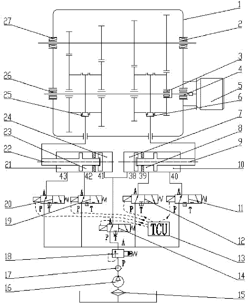
[0021] refer to figure 1 , The electro-pneumatic-mechanical automatic shifting system of the present invention is composed of a gearbox 1, a motor 5, a pneumatic control system and an electronic control unit (TCU) 13.

[0022] The end cover of the motor 5 is fixedly connected with the right end face of the box body of the gearbox 1 through bolts, the input shaft of the gearbox 1 is directly connected with the output end of the output shaft of the motor 5 through a spline pair, and the right end of the input shaft of the gearbox 1 is connected through 2 The No. 1 cylindrical roller bearing 4 is installed on the right box wall of the gearbox 1 to form a rotational connection, and the right end of the output shaft of the gearbox 1 is inserted into the left end of the input shaft of the gearbox 1 by means of the No. 1 cylindrical roller bearing 3 The axial inner hole of the gearb...


PUM


Abstract

The invention discloses an electric control pneumatic mechanical automatic shift system which comprises a transmission case (1), a motor (5), a pneumatic control system and an electric control unit(13), wherein the pneumatic control system comprises a 3-gear and 4-gear shift air cylinder (9), a No 5 electromagnetic valve (11), a No 4 electromagnetic valve (12), a No 3 electromagnetic valve (14), a No 2 electromagnetic valve (19), a No 1 electromagnetic valve (20), and a 1-gear and 2-gear shift air cylinder (22); the No 2 piston of the 1-gear and 2-gear shift air cylinder (22) is connected with a 1-gear and 2-gear shifting yoke of the transmission case (1), and the No 2 piston (32) of the 3-gear and 4-gear shift air cylinder (9) is connected with a 3-gear and 4-gear shifting yoke of the transmission case (1); the motor(5) is fixedly connected with the transmission case (1), and the spline pair of the input shaft of the transmission case (1) is connected with the output end of the motor (5); and the terminals of electromagnetic coils from the No 1 electromagnetic valve (20) to the No 5 electromagnetic valve (11) are connected with a wire of the electric control unit (13).

Description

technical field [0001] The present invention relates to a shifting system for electric vehicles and hybrid vehicles, more particularly, the present invention relates to an electro-pneumatic mechanical automatic shifting system for electric vehicles and hybrid vehicles. Background technique [0002] As people pay more and more attention to the protection of the environment and the effective and reasonable use of energy, electric vehicles with high efficiency, energy saving and environmental protection have gradually become the development trend of the automobile industry. Traditional electric vehicles and hybrid vehicles do not need to set multiple gears because the motor itself can be adjusted in speed and can be started with a load, so there is no need to set a clutch. However, if you want this kind of traditional electric vehicles and hybrid vehicles to run at high speed, the motor must have a very high speed. However, the characteristics of the motor are constant power ou...

Claims


Application Information

Patent Timeline
Patent Type & Authority Applications(China)
IPC IPC(8): F16H61/40
Inventor 雷雨龙刘振杰郑鸿鹏吕二华李兴忠孙少华文杰桃王昌
Owner JILIN UNIV
Why Eureka
Try Eureka