
Alternating-current LED (light emitting diode) illumination device

A technology of light-emitting diodes and lighting devices, which is applied to lighting devices, components of lighting devices, lighting and heating equipment, etc., and can solve problems such as reduced luminous efficiency, reduced power utilization efficiency of light-emitting diode lighting devices, and shortened lifespan

Inactive Publication Date: 2012-02-01
FOXSEMICON INTEGRATED TECHNOLOGY (SHANGHAI) INC +1
View PDF4 Cites 0 Cited by
  • Summary
  • Abstract
  • Description
  • Claims
  • Application Information

AI Technical Summary

Problems solved by technology

However, the luminous efficiency of the LED will decrease with the increase of the injected current, and at the same time, the increase of the current will also make the LED junction temperature too high, shortening the life of the LED
In order to reduce the heat generated when the LED is working, the pulse width modulation (Pulse Width Modulation Dimming, PWMDimming) method can be used to control the switching state of the LED, but the PWM control method still needs to be operated under the state of constant current, so that the driving of the LED At least one AC-DC converter is included in the circuit, which reduces the power utilization efficiency of the entire LED lighting device and increases the cost

Method used


Image

  • Alternating-current LED (light emitting diode) illumination device
  • Alternating-current LED (light emitting diode) illumination device
  • Alternating-current LED (light emitting diode) illumination device

Examples


Embodiment Construction

[0027] The present invention will be further described in detail below in conjunction with the accompanying drawings.

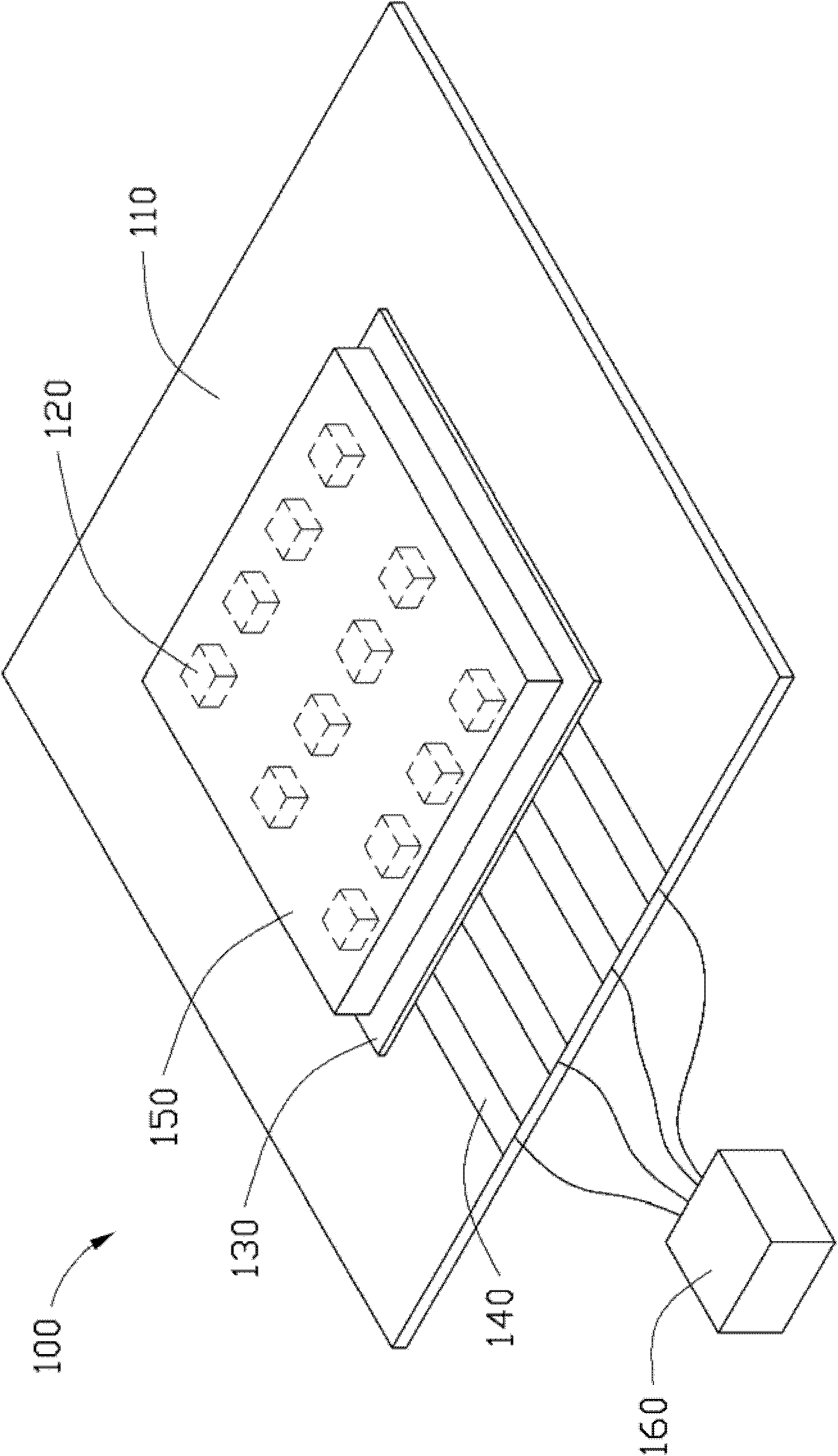
[0028] see figure 1 An AC LED lighting device 100 provided in the first embodiment of the present invention includes a heat dissipation substrate 110 , a plurality of LED chips 120 , a circuit layer 130 , an electrode 140 , a packaging layer 150 , and a driving unit 160 .

[0029] The heat dissipation substrate 110 is made of an insulating material with high thermal conductivity, such as silicon nitride (Si 3 N 4 ), silicon carbide (SiC), zirconia (ZrO 2 ), boron carbide (B 4 C), titanium diboride (TiB 2 ), alumina (Al x o y ), aluminum nitride (AlN), beryllium oxide (BeO) or a mixture of the aforementioned materials, etc. In addition, the heat dissipation substrate 110 can also be a conductive substrate coated with an insulating material.

[0030] The plurality of LED chips 120 are disposed on a surface of the heat dissipation substrate 110 . The pl...


PUM


Abstract

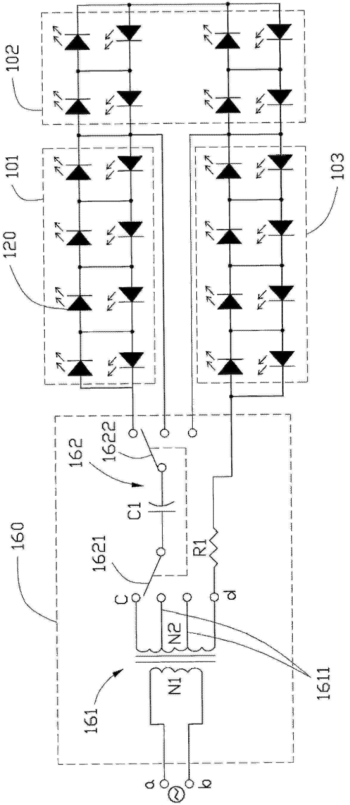
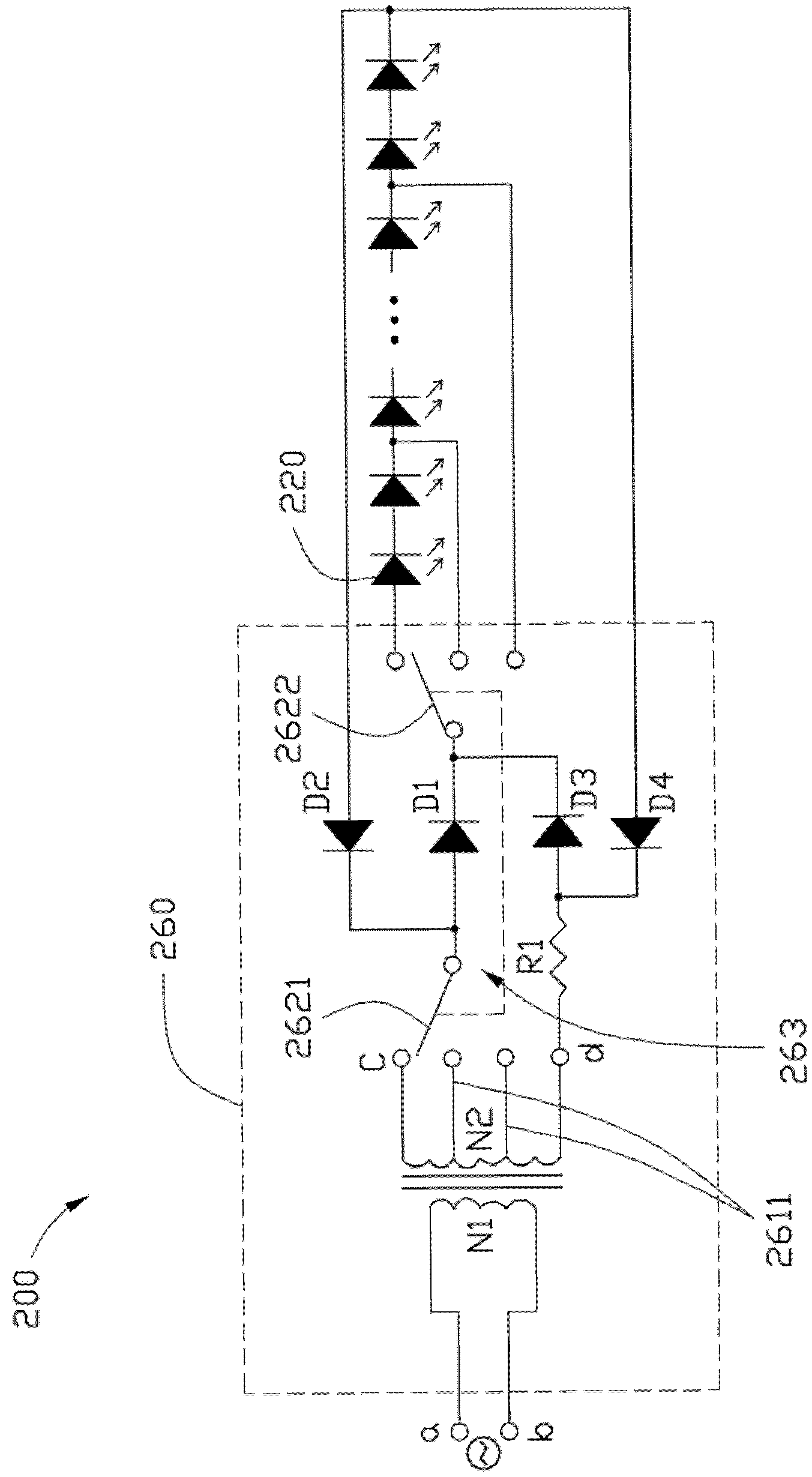
The invention relates to an alternating-current LED (light emitting diode) illumination device which comprises a heat radiation substrate, a plurality of LED chips arranged on the heat radiation substrate, a circuit layer, a packaging layer, an electrode exposing out of the packaging layer and a driving unit; the plurality of LED chips are combined into at least two groups of serial LED chip sets, and each group of LED chip set comprises at least two reversely parallel LED chips; the driving unit comprises a transformer and a bilaterial switch; one end of a first switch in the bilaterial switch is selectively connected with the output end of the transformer so that the driving unit ouputs driving voltages with different sizes to the plurality of LED chips; one end of a second switch in the bilateral switch is connected with the first switch, and the other end of the second switch is selectively connected with partial or all of the plurality of LED chips electrically.

Description

technical field [0001] The invention relates to a light-emitting diode lighting device, in particular to a light-emitting diode lighting device driven by alternating current. Background technique [0002] Currently, light emitting diodes (Light Emitting Diodes, LEDs) are widely used in many fields due to their good light quality and high luminous efficiency. Since the luminous intensity of LED is almost directly proportional to the injected current, most of them use direct current to drive LED to emit light. However, the luminous efficiency of the LED will decrease with the increase of the injected current, and at the same time, the increase of the current will also cause the junction temperature of the LED to be too high, shortening the life of the LED. In order to reduce the heat generated when the LED is working, the pulse width modulation (Pulse Width Modulation Dimming, PWMDimming) method can be used to control the switching state of the LED, but the PWM control method...

Claims


Application Information

Patent Timeline
IPC IPC(8): F21S4/00F21V19/00F21V23/00F21V23/04F21V23/06F21Y101/02F21Y115/10
Inventor 孔圣翔赖志铭
Owner FOXSEMICON INTEGRATED TECHNOLOGY (SHANGHAI) INC
Learn More