A Damper

A technology of damping mechanism and damping oil, which is applied in building structure, door/window fittings, wing leaf parts, etc. It can solve the problems of limited oil tank area, increased weight of toilet cover, and limited installation space, etc., and achieves a simple and compact structure , prevent impact, increase the effect of damping effect

Active Publication Date: 2013-06-05
柳志芳
View PDF3 Cites 0 Cited by
  • Summary
  • Abstract
  • Description
  • Claims
  • Application Information

AI Technical Summary

Problems solved by technology

[0003] However, in the existing toilet damping and slow-down mechanism, the one-way vane is used as the oil circuit switch to block the damping oil in one direction, thereby realizing one-way damping, but the gap between the one-way vane and the housing is often caused by manufacturing errors and deformation. And other reasons can not make the oil circuit completely closed, can not play a good damping effect, so for the damping effect, the industry has appeared various damping mechanisms
However, the existing damping mechanism is only made of toilet lids made of plastic materials with limited weight.
With the improvement of people's quality of life, different groups of people will choose sanitary products of different materials. For example, the toilet cover will also be made of wood or other more textured materials, which will inevitably increase the weight of the toilet cover. For heavy toilet covers or other covers such as piano keys, due to the limited installation space at the rear of the cover, the size of the mechanism cannot be enlarged, the area of ​​the fuel tank is limited, and the pressure is limited. The existing damping mechanism cannot guarantee the damping effect. This case is convenient. resulting from

Method used


Image

  • A Damper
  • A Damper
  • A Damper

Examples


Embodiment Construction

[0082] The present invention will be further described below in conjunction with accompanying drawing.

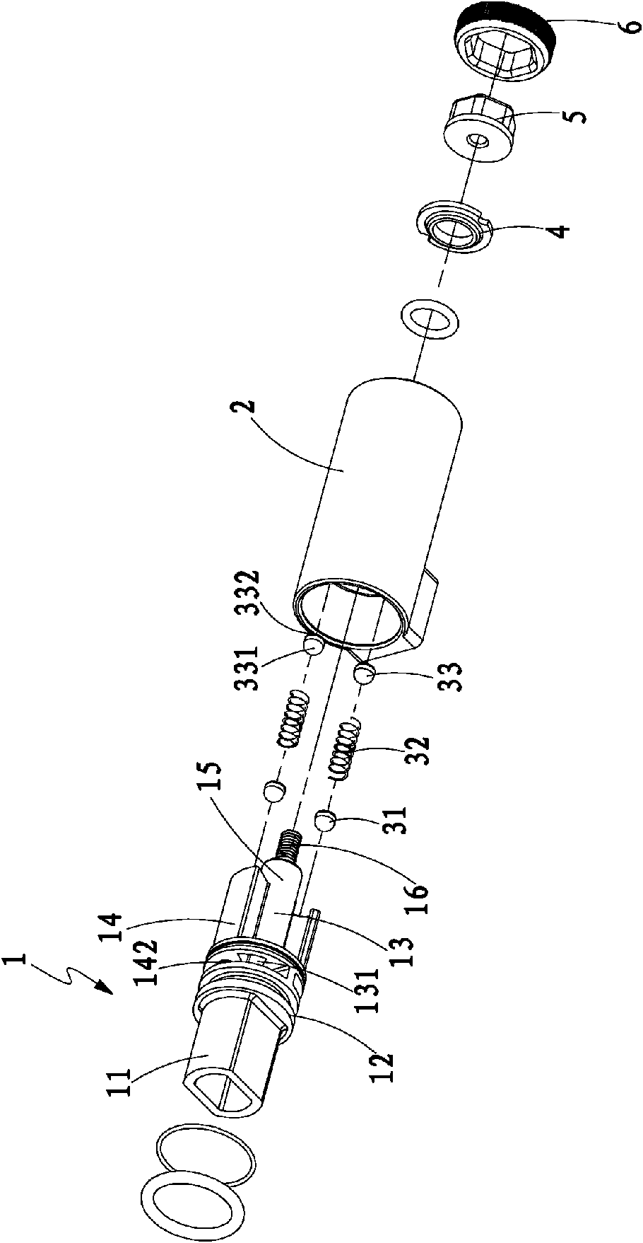
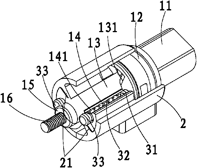
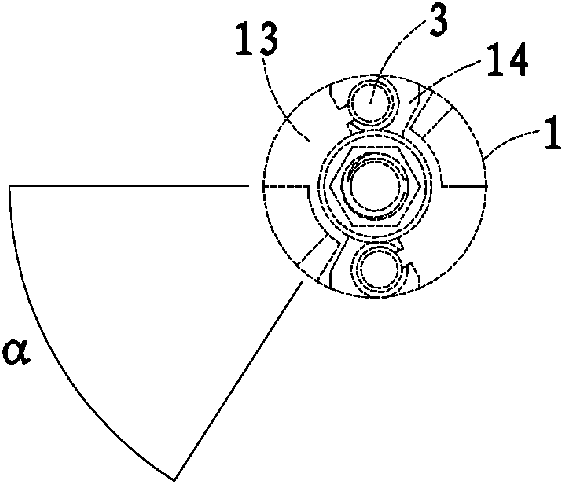
[0083] Such as Figure 1 to Figure 2-6 As shown, a damping mechanism disclosed by the present invention includes a rotating shaft 1, a shaft sleeve 2, a damping device 3, damping oil, a sealing ring 4, a nut 5 and a shaft sleeve fixing member 6; the sealing ring 4, the nut 5 and The shaft sleeve fixing part 6 forms a connecting part between the rotating shaft 1 and the shaft sleeve 2 . Here, the application to the toilet cover is taken as an example for illustration.

[0084] The rotating shaft 1 is assembled in the shaft sleeve 2, and the shaft 1 is provided with a special-shaped matching part 11 which is matched with the cover plate E, and a flange 12 is provided adjacent to the matching part to sleeve the sealing member and the shaft sleeve 2 for sealing fit. Adjacent to the flange 12, there are two symmetrical matching grooves 13 extending toward the front of the rota...


PUM


Abstract

A damper includes a rotary shaft, a sleeve, damping oil, and the damping oil is filled in a closed chamber formed between the rotary shaft and the sleeve; cooperating grooves are formed on the rotary shaft; partition parts are formed between the two cooperating grooves; oil passing holes provided on the partition parts are communicated with the two cooperating grooves; the oil passing holes are controlled by the check valves to make the damping oil flow in a single direction between the two cooperating grooves; the rotary shaft passing through the cooperating hole on the necking stop wall of the sleeve is connected by a connection member; two spacers are integrated with the sleeve; the height of the spacers locating in the cooperating grooves just fits in with the depth of the cooperating groove; an oil passing gap formed between the rotary shaft and the sleeve and is variable.

Description

technical field [0001] The invention relates to a damping mechanism applied to an opening and closing device, in particular to a damping mechanism that enables the opening and closing device to be opened without damping, but to generate damping when closing, so as to prevent impact damage. Background technique [0002] The damping mechanism is widely used on some movable lids that can be opened and closed, and usually has a one-way damping effect. For example, when it is applied to the toilet lid, there is no damping effect when the toilet lid is lifted, but when the toilet lid falls The damping effect is generated during the process, so that the cover plate will fall slowly without impacting the toilet. [0003] However, in the existing toilet damping and slow-down mechanism, the one-way vane is used as the oil circuit switch to block the damping oil in one direction, thereby realizing one-way damping, but the gap between the one-way vane and the housing is often caused by ...

Claims


Application Information

Patent Timeline
Patent Type & Authority Patents(China)
IPC IPC(8): A47K13/10
CPCE05Y2900/614E05F5/02E05Y2201/234A47K13/12E05Y2201/21E05Y2201/266
Inventor 柳志芳
Owner 柳志芳
Why Eureka
Try Eureka