
Reversible oil pan with integrated oil suction tube

A technology of oil pan and suction pipe, applied in the field of reversible oil pan with integrated oil suction pipe

Inactive Publication Date: 2012-02-01
CUMMINS LTD
View PDF4 Cites 4 Cited by
  • Summary
  • Abstract
  • Description
  • Claims
  • Application Information

AI Technical Summary

Problems solved by technology

[0004] One problem with current oil pans and their production methods is the use of many different types of suction tubes and / or oil pans for different vehicle builds

Method used


Image

  • Reversible oil pan with integrated oil suction tube
  • Reversible oil pan with integrated oil suction tube
  • Reversible oil pan with integrated oil suction tube

Examples


Embodiment Construction

[0013] The present invention relates to an oil pan for collecting oil in vehicles and other machines, and more specifically, the present invention relates to an oil pan using an oil suction pipe. The following description is proposed to enable those of ordinary skill in the art to implement and use the present invention, and in the context of the patent application and its requirements, the following description is provided. For those skilled in the art, various modifications to the preferred embodiments and general principles and features described herein will be obvious. Therefore, the present invention is not intended to be limited to the illustrated embodiments, but should be granted the widest scope consistent with the principles and features described herein.

[0014] The present invention is mainly described in terms of specific components provided in specific implementations. However, those of ordinary skill in the art will readily recognize that the device will operate ...


PUM


Abstract

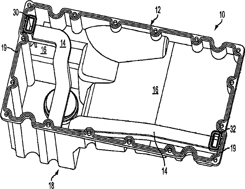
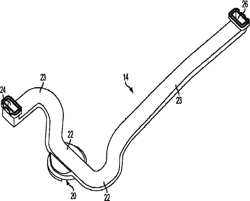
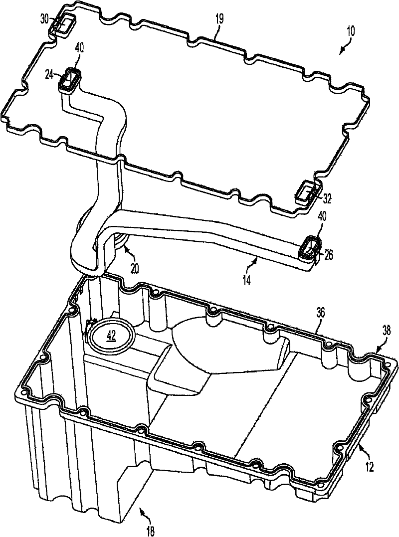
The present invention relates to a reversible oil pan assembly including an oil suction tube. In one aspect, an oil pan assembly includes an oil pan and a suction tube connected to the oil pan. The suction tube includes an inlet to draw oil from the oil pan, and a plurality of outlets, each outlet configured to output oil that has been moved through the suction tube from the inlet.

Description

Technical field [0001] The present invention relates to an oil pan for collecting oil in vehicles and other machines, and more specifically, the present invention relates to an oil pan using an oil suction tube. Background technique [0002] Motor vehicles and other machines use oil to lubricate the moving parts of the machine. In many vehicle implementations, oil is provided and collected in an oil pan as a reservoir. The oil pump sucks oil from the bottom of the oil pan through a pipe to circulate the oil in the vehicle. For example, use an oil pump to pressurize the oil and pump it through an oil filter to remove grit. The oil is supplied from the oil pump to other components of the engine or vehicle, such as bearings, turbochargers, and pistons. For example, oil can be supplied to the crankshaft and connecting rod bearings and to the wall of the cylinder located in the internal combustion engine, and eventually drips from the wall due to gravity into the bottom of the cran...

Claims


Application Information

Patent Timeline
Patent Type & Authority Applications(China)
IPC IPC(8): F01M11/00F01M11/02F01M11/03
CPCF01M2011/007F01M2011/005F01M11/0004F01M2011/0091F01M11/02F01M11/03
Inventor 詹姆斯·多德斯韦恩·斯普纳马修·克拉克保罗·理查德·托金
Owner CUMMINS LTD
Learn More