
Field installation process of large-span high-water-head hydraulic driving type steel dam gate

A field-installed, high-head technology, applied in water conservancy projects, sea area projects, coastline protection, etc., can solve the problems of increasing production costs, high requirements for transportation equipment and transportation lines, high lifting costs, etc., and achieve the effect of improving work efficiency

Inactive Publication Date: 2012-02-08
中国水利水电第十三工程局有限公司第二分公司
View PDF5 Cites 5 Cited by
  • Summary
  • Abstract
  • Description
  • Claims
  • Application Information

AI Technical Summary

Problems solved by technology

The problems of this construction process are: 1. The existing equipment has a large size, and a large assembly workshop and heavy lifting equipment are required; 2. The transportation conditions of the existing equipment are harsh, and only water transportation is available, which requires equipment processing and manufacturing plants. It must be close to the wharf, and extra-large lifting equipment must be used for lifting during transportation; 3. Due to the limitation of the processing site, the equipment processing can only be manufactured and debugged with a single hole, and the production and debugging of the porous gate will take a long period of time, and it is difficult to realize flow construction , and increased production costs; 4. Large-scale hoisting equipment and large-tonnage barges are used in transportation, which is difficult to implement and is a high-risk operation, and the hoisting cost is high
5. It is very difficult to transport the overall assembly gate with super heavy weight, and the requirements for transportation equipment and transportation lines are high. At the same time, the technical difficulty of on-site installation and debugging is increased, and the production cost is increased.

Method used


Image

  • Field installation process of large-span high-water-head hydraulic driving type steel dam gate

Examples


Embodiment Construction

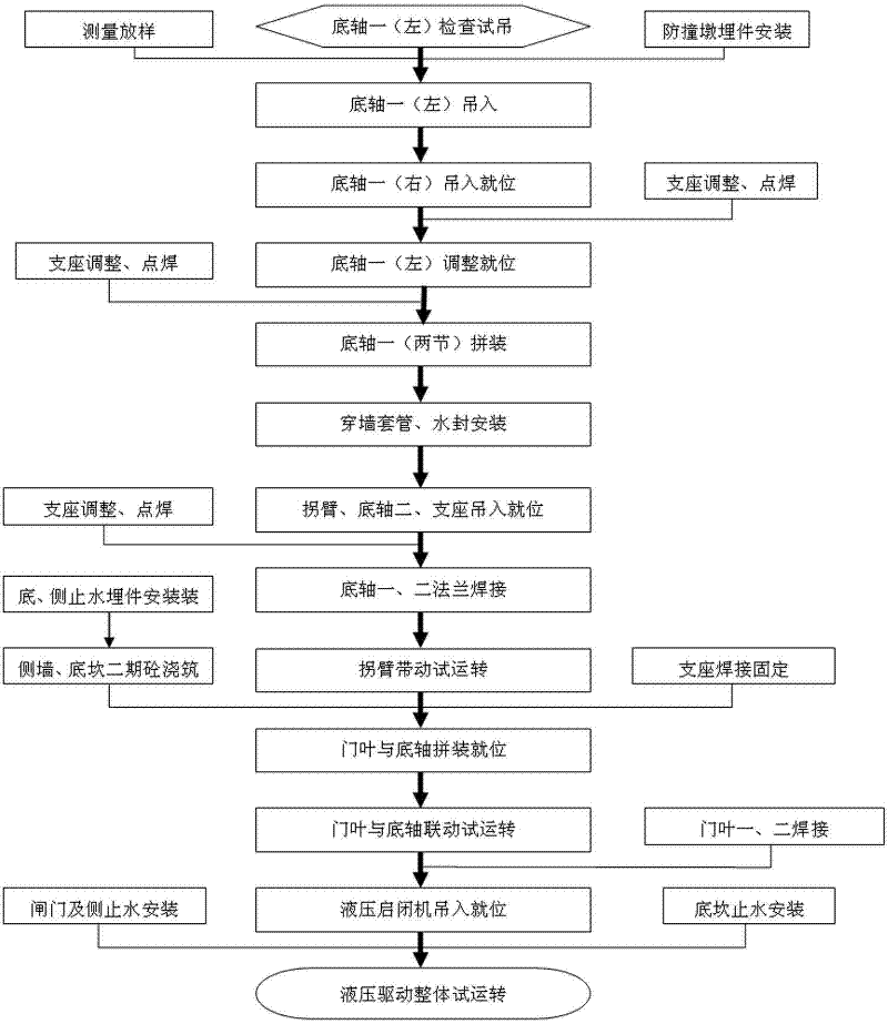
[0031] As shown in the figure; the technical solution of the present invention is realized in this way:

[0032] 1. Bottom shaft tube installation

[0033] 1.1 After the bottom shaft one (right) is hoisted in, advance 3.7m to the inner side of the gate pier, and the other end is 2.8m away from the centerline of the gate hole.

[0034] 1.2 Bottom shaft 1 (left) is hoisted in directly, and after it is basically in place according to the actual control line, make accurate adjustments. ①Plane adjustment: first use the total station installed on the top of the gate pier to observe the actual deviation, and then use the crane to lift the bottom shaft tube again. When lifting, the bottom shaft tube should not be separated from the contact point; use the jack or chain hoist that has been prepared on site. Fine-tuning, the control error is 0~1mm, and the error after overall assembly is 0~3mm; after accurate adjustment, the connecting plate of the support is fixed by spot welding. ②El...


PUM


Abstract

The invention relates to a field installation process of a large-span high-water-head hydraulic driving type steel dam gate, belonging to the technical field of water conservancy engineering. In the field installation process of the hydraulic bottom-shaft driving type flap gate, all related members and parts are respectively manufactured in a manufacturer by dismemberment, and are transported to a construction site in batches for field installation and staged debugging. The installation process flow comprises the following steps of: lifting preparation of a bottom shaft I and a support assembly part, in-place lifting, position adjustment of elevation and planes, wall penetration and pipe sheathing, water seal installation, in-place lifting of a crank arm, a bottom shaft II and the support assembly part, welding of the bottom shaft I and the bottom shaft II by a flange, rotary debugging of the crank arm and the bottom shafts, installation, adjustment and secondary concreting of bottom sills and gate pier side-wall embedding pieces, assembly of gate flaps and the bottom shafts, idle-load debugging, water stopping installation, installation of a hydraulic opening and closing machine and single-hole debugging. The field installation process is safe and reliable; the technical difficulty in transportation, installation and debugging and the production cost are reduced; the working efficiency is improved; and a successful example is provided for the technical field.

Description

technical field [0001] The invention belongs to the technical field of hydraulic engineering. Background technique [0002] At present, similar gates have been built in China, and all components and parts of the gates are processed in the manufacturing plant, and the manufacture and assembly of the bottom shaft, door leaf, bearing assembly, bottom water stop, etc. are completed in sequence according to the manufacturing process; after the manufacturing is completed, The gate is debugged in the factory, and after the overall assembly is completed, it is transported to the gate site together with the concrete bottom plate and placed in place. The problems of this construction process are: 1. The existing equipment has a large size, and a large assembly workshop and heavy lifting equipment are required; 2. The transportation conditions of the existing equipment are harsh, and only water transportation is available, which requires equipment processing and manufacturing plants. ...

Claims


Application Information

Patent Timeline
IPC IPC(8): E02B7/40
Inventor 张高飞佡红张世越陈鹏
Owner 中国水利水电第十三工程局有限公司第二分公司
Learn More