
Self-propelled drilling method and pulsed cavitation swirling jet nozzle

A drilling method and jet nozzle technology, which are applied in the direction of drilling with liquid/gas jets, etc., can solve the problems of low jet energy utilization efficiency, irregular orifice passages, rotational sealing resistance, etc., so as to improve energy transfer efficiency, reduce energy loss, The effect of improving the erosion performance

Active Publication Date: 2012-02-08
CHINA UNIV OF PETROLEUM (BEIJING)
View PDF5 Cites 26 Cited by
  • Summary
  • Abstract
  • Description
  • Claims
  • Application Information

AI Technical Summary

Problems solved by technology

The multi-hole nozzle is to change the single-hole nozzle into a multi-hole nozzle, and increase the erosion area through the multiple jets generated by it, but this method requires a higher jet flow rate, and because the crushing method is still impact crushing, the jet energy utilization efficiency is low
And the channels formed by its reverse jet flow are not regular enough
The mechanical rotary nozzle jet uses hydraulic or mechanical energy to drive the entire nozzle to rotate, thereby driving the multi-nozzles distributed on the nozzle to rotate. This rotation driving method has the problems of rotation sealing resistance and life, and the efficiency of jet energy utilization is relatively low.

Method used


Image

  • Self-propelled drilling method and pulsed cavitation swirling jet nozzle
  • Self-propelled drilling method and pulsed cavitation swirling jet nozzle
  • Self-propelled drilling method and pulsed cavitation swirling jet nozzle

Examples


Embodiment Construction

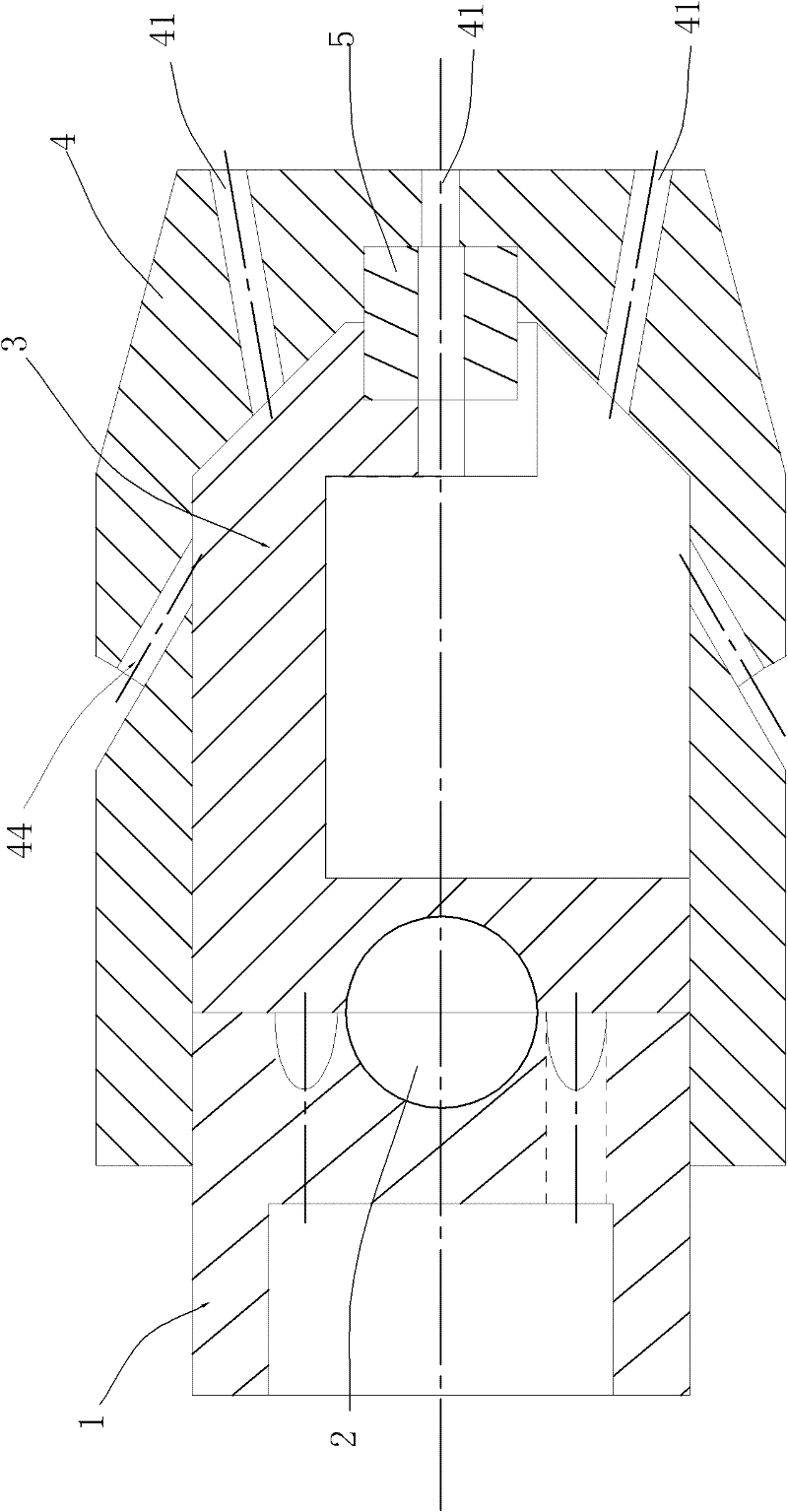
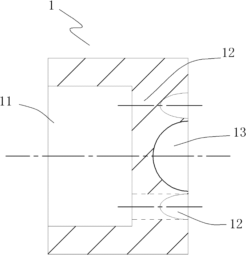
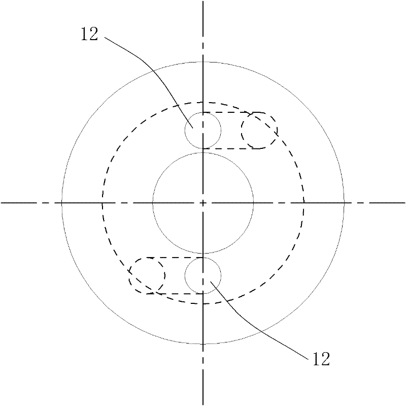
[0031] The self-propelled drilling method proposed by the invention is a mixed jet drilling method formed by coupling the pulse jet method, the cavitation jet method and the rotating jet method. Wherein, the impeller body arranged in the nozzle rotates under the impact of the fluid, and when the impeller body rotates, it can close a part of the forward injection port arranged on the nozzle head and be arranged on the nozzle in the direction opposite to the direction of the forward injection port. The fluid is sprayed from the other part of the forward jet port and the reverse jet port provided on the nozzle head to form a jet, and a part of the forward jet port and the reverse jet port are alternately closed during the rotation of the impeller body. In addition, the rotation of the impeller body drives the fluid entering the nozzle to rotate, and when the fluid that generates rotation is ejected from the forward injection port, a rotating jet is generated; and the The rotation...


PUM

PropertyMeasurementUnit
Angleaaaaaaaaaa
Angleaaaaaaaaaa

Abstract

The invention relates to a self-propelled drilling method and a nozzle. The self-propelled drilling method is formed by coupling a pulsed jet method, a cavitation jet method and a swirling jet method, wherein, an impeller body arranged in the nozzle can rotate under the impact action of a fluid, a part of forward jet orifices arranged at the head of the nozzle as well as a part of backward jet orifices which are arranged on the nozzle and are opposite to the forward jet orifices can be closed during the rotation process of the impeller body, the fluid is ejected from the other part of the forward jet orifices and the backward jet orifices so as to form jet flow, and the forward jet orifices are alternately closed so as to generate pulsed jet during the rotation process of the impeller body; the fluid entering the nozzle is driven to rotate by the rotating impeller body, and then the rotating fluid is ejected from the jet orifices so as to generate swirling jet; and the central pressure in the nozzle can be reduced by means of rotation of the impeller body so as to form cavitation jet. In the self-propelled drilling method, advantages of the three types of jet flow are integrated so as to greatly improve the drilling efficiency; and the self-propelled drilling method and the nozzle are applicable to drilling holes in a ground layer.

Description

technical field [0001] The invention relates to a drilling method and a nozzle, especially a drilling method capable of generating vibration and self-propelling force, coupling of pulse jet, cavitation jet and rotating jet to form a mixed combined jet, and capable of realizing The method for a self-advancing pulsed cavitation rotating jet nozzle. Background technique [0002] In real life, we need to drill holes in formations in many situations. For example, laying optical fiber cables, transportation pipelines and drilling ventilation channels in coal mines and oil and gas drainage channels in oil wells or gas wells. The method of using high-pressure water jet to drill laterally in the reservoir of oil well, and then increase the drainage area of ​​oil and gas has been extensively studied. [0003] The currently widely used jet methods mainly include: continuous straight jet, pulse jet, rotating jet and cavitation jet. And these jet flow methods all have some defects. s...

Claims


Application Information

Patent Timeline
IPC IPC(8): E21B7/18
Inventor 李根生黄中伟牛继磊马东军田守嶒史怀忠宋先知
Owner CHINA UNIV OF PETROLEUM (BEIJING)
Learn More