
Blind detection method

A technology of blind detection and carrier, which is applied in the field of blind detection, can solve the problems of huge number of blind detection times, increased UE battery loss, high probability of false detection, etc., and achieve the effect of reducing the probability of false detection and battery loss, and reducing the number of blind detection times

Inactive Publication Date: 2012-02-08
POTEVIO INFORMATION TECH
View PDF9 Cites 26 Cited by
  • Summary
  • Abstract
  • Description
  • Claims
  • Application Information

AI Technical Summary

Problems solved by technology

Since in the search space allocated to the UE, the UE does not know the number of DCIs that require blind detection, it needs to perform blind detection according to the maximum number of blind detection times. The number of blind detections is very large, which will undoubtedly increase the battery consumption of the UE. Moreover, blind detection The more detection times, the greater the possibility of error, that is, the greater the probability of false detection, because of its performance loss

Method used


Image

  • Blind detection method
  • Blind detection method
  • Blind detection method

Examples


Embodiment Construction

[0027] Aiming at the problems existing in the prior art, the present invention proposes a brand-new blind detection method, which can reduce the probability of false detection and battery loss.

[0028] In order to make the technical solution of the present invention clearer and clearer, the solution of the present invention will be further described in detail below with reference to the accompanying drawings and examples.

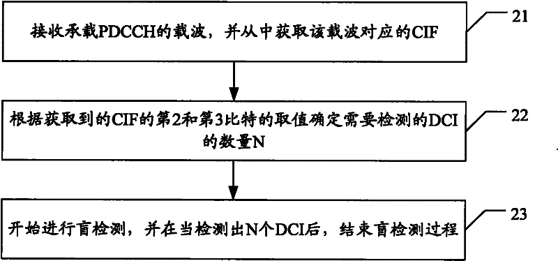
[0029] figure 2 It is a flowchart of an embodiment of the blind detection method of the present invention. like figure 2 shown, including the following steps:

[0030] Step 21: Receive the carrier carrying the PDCCH, and obtain the CIF corresponding to the carrier from it.

[0031] Step 22: Determine the number N of DCIs to be detected according to the obtained values ​​of the second and third bits of the CIF.

[0032] According to the previous introduction, in general, each component carrier corresponds to 3 DCIs, and one of the DCIs is set with a C...


PUM


Abstract

The invention provides a blind detection method, which comprises the following steps: receiving a carrier which carries a physical downlink control channel (PDCCH), and acquiring a carrier indicator field (CIF) corresponding to the carrier from the carrier, wherein the CIF comprises three bits in all; determining the number N of downlink control information (DCI) needed to be detected according to the values of a second bit and a third bit of the acquired CIF; and carrying out blind detection, and ending the process of blind detection after N DCI is detected. With the adoption of the method provided by the invention, the error detection probability and the battery loss can be lowered.

Description

technical field [0001] The present invention relates to an advanced long-term evolution (LTE-A, Long Term Evolution-Advanced) technology, in particular to a blind detection method in the LTE-A technology. Background technique [0002] The LTE-A technology is a subsequent evolution technology of the LTE technology. In the traditional way, the target peak rate, such as 1Gbits / S rate, can be obtained through 100MHz or more continuous bandwidth, but in most cases, spectrum competition makes it unrealistic to obtain such a large continuous bandwidth, for Therefore, a carrier aggregation technology is proposed in the LTE technology, that is, a larger bandwidth requirement is met by aggregating two or more basic carriers. figure 1 It is a schematic diagram of an existing carrier aggregation mode. [0003] In the LTE-A technology, in the downlink direction, each user terminal (UE) can support a maximum of 5 component carriers (CC, Component Carrier) (the uplink direction is also 5...

Claims


Application Information

Patent Timeline
Patent Type & Authority Applications(China)
IPC IPC(8): H04L25/02H04L1/00H04L27/26
Inventor 鲁智
Owner POTEVIO INFORMATION TECH
Learn More