Hydraulic array for roller mills

A grinding machine and grinding technology, applied in the field of hydraulic system devices, can solve problems such as pressure rise, high pipeline costs, and hysteresis, and achieve the effect of reducing damage and avoiding pollution

Inactive Publication Date: 2012-02-08
LOESCHE GMBH
View PDF11 Cites 3 Cited by
  • Summary
  • Abstract
  • Description
  • Claims
  • Application Information

AI Technical Summary

Problems solved by technology

[0010] Disadvantages of the known systems with hydraulic cabinets for the individual roller pairs are that the costs for producing and assembling the pipes, especially for the laying of the pipes, are too high, the components of the hydraulic system due to contamination that cannot be completely avoided under field assembly conditions Whereas the risk of accidental damage is relatively high and the possibility of repair and replacement of the hydraulic system or individual components is relatively low in the event of damage
However, for the general function "increased operating pressure", a larger pump power is disadvantageous, since too much oil is already delivered to the system during a brief switch-on of the larger pump, resulting in a rapid increase in pressure, This elevated pressure then exceeds the standard value and leads to a command to re-enable the "operating pressure drop" in the hydraulic system
Therefore there is often hysteresis in this conversion process

Method used


Image

  • Hydraulic array for roller mills
  • Hydraulic array for roller mills
  • Hydraulic array for roller mills

Examples


Embodiment Construction

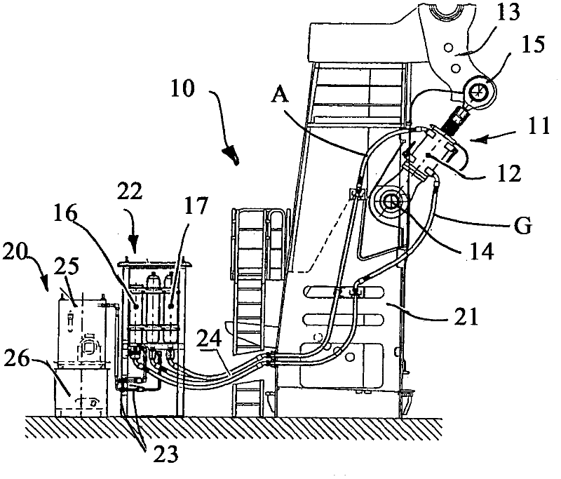
[0030] figure 1 Shown is a hydropneumatic spring system 10 for a LOESCHE type air roller mill of modular design. According to the invention, a spring unit 11 is assigned to each grinding roller (not shown).

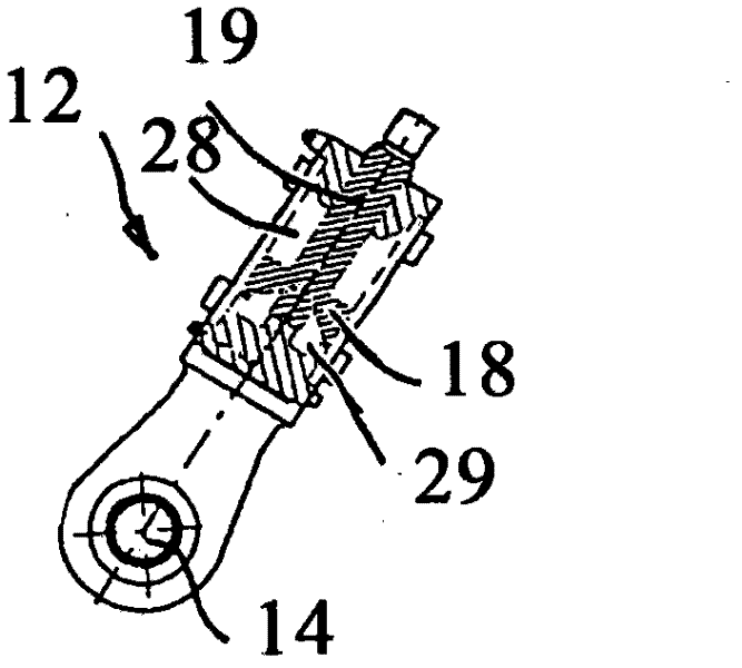
[0031] The spring unit 11 of each grinding roller has one or two hydraulic cylinders 12 depending on the size of the roller module (and thus especially the size of the grinding roller), which are connected to the grinding roller via a swing rod 13 Rollers (not shown) are attached. The hydraulic cylinder 12 is fastened to the frame 21 or to the mill floor via the pivot hole 14 and to the pivot lever 13 via the connecting rod head 15 .

[0032] Each spring unit 11 of the grinding roll is assigned its own hydraulic supply unit 20 . The hydraulic supply unit 20 includes a motor-driven pump, valves and shut-off devices, a grinding pressure regulation system or electric control and operating elements for switching the different operating states of the roller springs.

[00...


PUM


Abstract

The invention relates to a hydraulic array for roller mills, having a spring unit (11) for each grinding roll, a gas/oil reservoir (16, 17) and hydraulic supply systems for changing the operation states of the spring units or grinding rolls. In order to ensure an almost constant crushing power and a uniform contact pressure of the grinding rolls and at the same time reduce the production and assembly costs and the risk of failure of the components of the hydraulic system and to improve the exchange of components or the entire system, each spring unit of a grinding roll is associated, in its proximity, with its proper hydraulic supply unit (20) as a compact hydraulic system and a reservoir station (22) so that the necessary connections can be realized by means of relatively short conduits (23) and high-pressure lines (24). Every hydraulic supply unit can be pre-assembled under dust-free ambient conditions and accommodated for example in a hydraulic cabinet (25) and only needs to be connected on site.

Description

technical field [0001] The invention relates to a hydraulic system arrangement for a roller mill according to the preamble of claim 1 . Background technique [0002] The invention is used in roller mills in which the milled material is milled between grinding discs or circulating horizontal grinding belts of grinding discs and stationary rolling grinding rollers, and the roller mill Overflow mills that are configured to drop the milled ground material down from the edge of the grinding disc or the edge of the grinding disc or are configured to convey the ground material along the air or gas flow in an integrated sieve Air roller mill machine for crushing mills. [0003] It is particularly advantageous that the invention is suitable for large roller mills, for example large roller mills with a grinding disc diameter of 2 m and more and with three, four or six grinding rollers. For example, roller mills are known having a grinding disc diameter of 4.1 and 4.3 m, on which fou...

Claims


Application Information

Patent Timeline
Patent Type & Authority Applications(China)
IPC IPC(8): B02C15/04
CPCB02C15/04
Inventor 德克·格鲁伯迈克尔·克斯勒
Owner LOESCHE GMBH
Why Eureka
Try Eureka