
Pneumatic-type intermediate-shaft braking system and braking method

A technology of braking system and intermediate shaft, which is applied in the direction of axial brake, brake type, brake actuator, etc., can solve the problems of long shifting time, unusable, difficult shifting, etc., and achieves high braking torque, The effect of large effective area and long service life

Inactive Publication Date: 2012-02-15
一汽解放青岛汽车有限公司
View PDF4 Cites 5 Cited by
  • Summary
  • Abstract
  • Description
  • Claims
  • Application Information

AI Technical Summary

Problems solved by technology

[0012] The pneumatic intermediate shaft braking system and braking method described in the present invention mainly solve the shortcomings of the original intermediate shaft braking system, which has a short service life and cannot be used in the running process of the vehicle, and is also an automatic transmission without synchronizer. Provided a technical solution to improve the shift quality
The present invention is mainly designed for gearboxes without synchronizers, specifically to solve the problem of difficulty in shifting gears when a gearbox without synchronizers is running, and can also be used in automatic gearboxes without synchronizers above, to solve the disadvantages of long shifting time or difficult shifting

Method used


Image

  • Pneumatic-type intermediate-shaft braking system and braking method
  • Pneumatic-type intermediate-shaft braking system and braking method
  • Pneumatic-type intermediate-shaft braking system and braking method

Examples


Embodiment 1

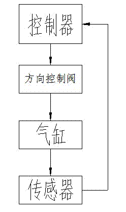
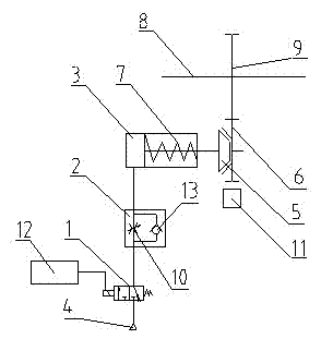
[0044] refer to figure 1 , figure 2 , to describe the embodiment of the present invention. The pneumatic intermediate shaft brake system described in this embodiment includes an air pressure source 4, a directional control valve 1, a cylinder 3, a return spring 7 and a power take-off gear 9, and also includes a speed regulating valve 2 and a friction cone 5 , brake gear 6, sensor 11 and controller 12, wherein air pressure source 4, directional control valve 1, cylinder 3 and speed regulating valve 2 are connected by air pipeline; brake gear 6 is meshed with power take-off gear 9; The sensor 11 is connected with the controller 12 by a wiring harness.

[0045] The sensor 11 is installed on the tooth top of the braking gear 6 , detects the rotation speed of the braking gear 6 , and transmits the rotation speed to the controller 12 . The controller 12 can calculate the working condition of the intermediate shaft brake system according to this information, and obtain the brakin...

Embodiment 2

[0053] refer to figure 1 , image 3 , to describe the embodiment of the present invention. The pneumatic intermediate shaft braking system and braking method described in this embodiment are basically the same as those in Embodiment 1, and the similarities with Embodiment 1 will not be repeated, and only the differences from Embodiment 1 will be described here. .

[0054] The difference is that the sensor 11 is installed at the tooth top of the power take-off gear 9 to detect the rotation speed of the power take-off gear 9 and transmit the rotation speed to the controller 12 . The controller 12 can calculate the working condition of the intermediate shaft brake system according to this information, and obtain the braking condition at this time.

[0055]

Embodiment 3

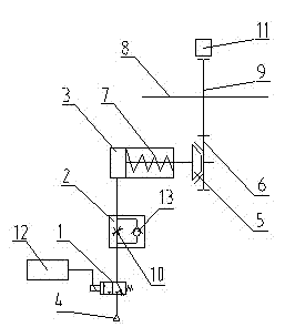
[0057] refer to figure 1 , Figure 4 , to describe the embodiment of the present invention. The pneumatic intermediate shaft braking system and braking method described in this embodiment are basically the same as those in Embodiment 1, and the similarities with Embodiment 1 will not be repeated, and only the differences from Embodiment 1 will be described here. .

[0058] The difference is that the sensor 11 is connected to the piston rod on the cylinder 3, and the axial displacement of the friction cone 5 can be detected by detecting the movement position of the piston rod. The controller 12 can calculate the working condition of the intermediate shaft brake system according to this information, and obtain the braking condition at this time.

[0059]


PUM


Abstract

The invention relates to a pneumatic-type intermediate-shaft braking system and a braking method. The pneumatic-type intermediate-shaft braking system mainly comprises an air-pressure source, a cylinder, a return spring and a power take-off gear, and in addition, the pneumatic-type intermediate-shaft braking system also comprises a direction-controlling valve, a speed-regulating valve, a frictioncone, a braking gear, a sensor and a controller, wherein the air-pressure source, the direction-controlling valve, the speed-regulating valve and the cylinder are sequentially connected through air pipelines; the speed-regulating valve is installed on a vehicle frame; the braking gear is installed on a supporting shaft and is engaged with the power take-off gear which is installed on an intermediate shaft in a gearbox; the friction cone is installed at the end part of a cylinder rod; the return spring is installed in the cylinder; and the sensor, the direction-controlling valve and the controller are connected through line bundles. The sensor can be used for detecting the rotating speed of the power take-off gear or the braking gear or can be used for detecting the axial displacement quantity of the friction cone. Through the pneumatic-type intermediate-shaft braking system and the braking method, the defect that an original intermediate-shaft brake system has a short service life andcan not be used in the driving process of a vehicle is mainly overcome, and meanwhile, a technical scheme for improving the gear-shifting quality is also provided for an automatic gearbox without adopting a synchronizer.

Description

[0001] technical field [0002] The invention relates to the technical field of automobiles, in particular to an automobile braking system and a braking method. [0003] Background technique [0004] The intermediate shaft brake is a gearbox auxiliary shifting mechanism. As the name suggests, it mainly brakes the intermediate shaft on the gearbox, reducing its speed through friction until it is in a locked state. The countershaft brake, as the actuator of the countershaft braking system, is mainly designed for gearboxes without synchronizers. Its original purpose is to lock one shaft and the intermediate shaft in the gearbox so that it cannot rotate when the clutch is disengaged during the starting process of the car, so as to facilitate gear shifting. After the non-synchronized gearbox adopts the intermediate shaft brake, the gear shifting at the start is relatively smooth, which can reduce the impact of the internal gears of the gearbox. To a certain extent, the problem...

Claims


Application Information

Patent Timeline
IPC IPC(8): F16D55/04F16D65/18F16D65/22F16D121/04F16D125/02
Inventor 王辛立王玉海王松董瑞先郑旭光张志欧
Owner 一汽解放青岛汽车有限公司
Learn More