Liquid crystal display and backlight module thereof

A backlight module and backplane technology, which is applied to lighting devices, fixed lighting devices, components of lighting devices, etc., can solve problems such as poor use, increased cost, and difficulty in removing the light bar 1.

Active Publication Date: 2012-02-15
TCL CHINA STAR OPTOELECTRONICS TECH CO LTD
View PDF6 Cites 22 Cited by
  • Summary
  • Abstract
  • Description
  • Claims
  • Application Information

AI Technical Summary

Problems solved by technology

[0003] Today's edge-lit backlight modules use LEDs as light sources, see Figure 1a and Figure 1b , first fix the LED light bar (Light bar) 1 to the fixing hole on the horizontal wall of the cooling block 2 through screws, and then fix the cooling block 2 through the screws in the fixing holes on the vertical wall of the cooling block 2 On the back panel 3, this installation method of the light bar 1 requires many procedures and high labor costs, and has the following disadvantages:
[0004] If heat-conducting adhesive is used to fix the light bar 1, it is difficult to remove the light bar 1 when it needs to be reworked later. Even if it can be removed, the light bar 1 will be deformed greatly, resulting in defects in subsequent use
[0005] If screws are used to fix the light bar 1, the LED pitch (spacing) is inconsistent between the place with screws and the place without screws, which requires mesh reinforcement on the light guide plate (not shown in the figure) at the place with screws. In order to prevent the module display from appearing dark blocks in the display area corresponding to the screw position due to inconsistent LED pitch, this requires high positioning of the light guide plate and the dot design of the light guide plate; The LED pitch of the screw position is not consistent, so the light mixing distance in the module design needs to be calculated according to the larger LED pitch, which makes the actual light mixing distance of the module larger; in addition, the head of the screw is exposed between the two LEDs. The distance between it and the two LED electrode solder feet is very small, which is prone to safety problems such as short circuit or high voltage ignition
Therefore, it is proposed to lock the screws from the back of the LED light bar, that is, to make a threaded blind hole on the PCB of the LED light to lock from the back with screws, which must increase the PCB board of the LED light bar. thickness, otherwise the screws cannot be locked, but the increase in the thickness of the PC board B of the LED light bar will lead to an increase in cost

Method used


Image

  • Liquid crystal display and backlight module thereof
  • Liquid crystal display and backlight module thereof
  • Liquid crystal display and backlight module thereof

Examples


Embodiment Construction

[0022] Below in conjunction with the best embodiment shown in the accompanying drawings, it will be further described in detail.

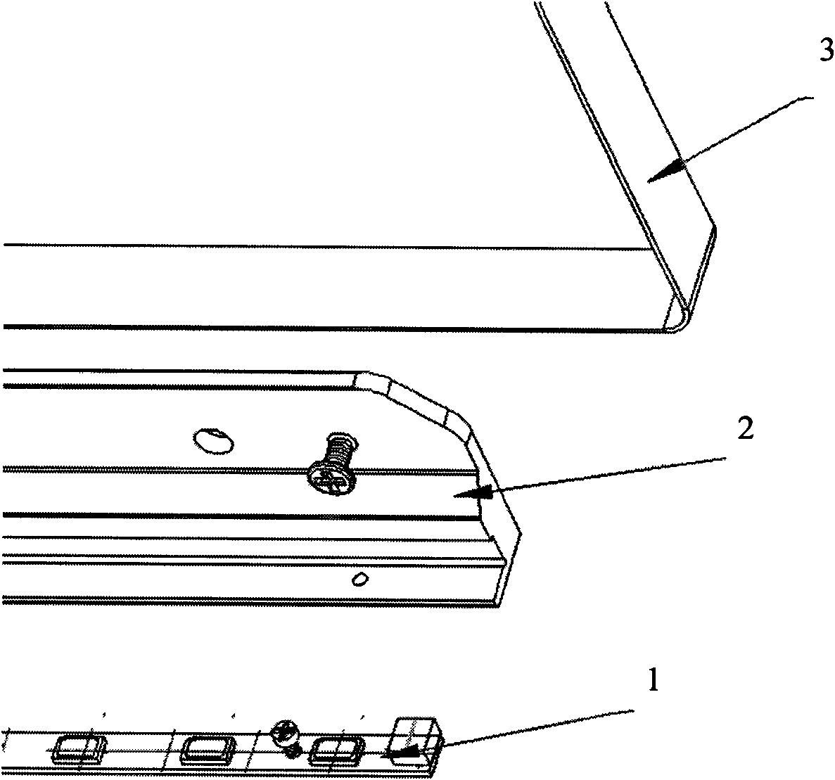
[0023] In the backlight module of the liquid crystal display device of the present invention, on the basis of the existing LED light bar, the heat dissipation block and the back plate structure, by adding a block with a mounting hole, with the help of the mounting hole on the block, it can be used tightly. The firmware fixes the LED light bar, the heat sink and the back plate together, so that many troubles caused by setting mounting holes on the light bar can be avoided.

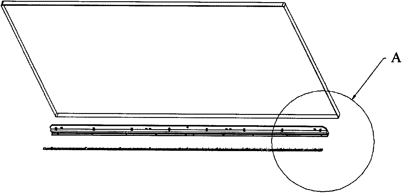
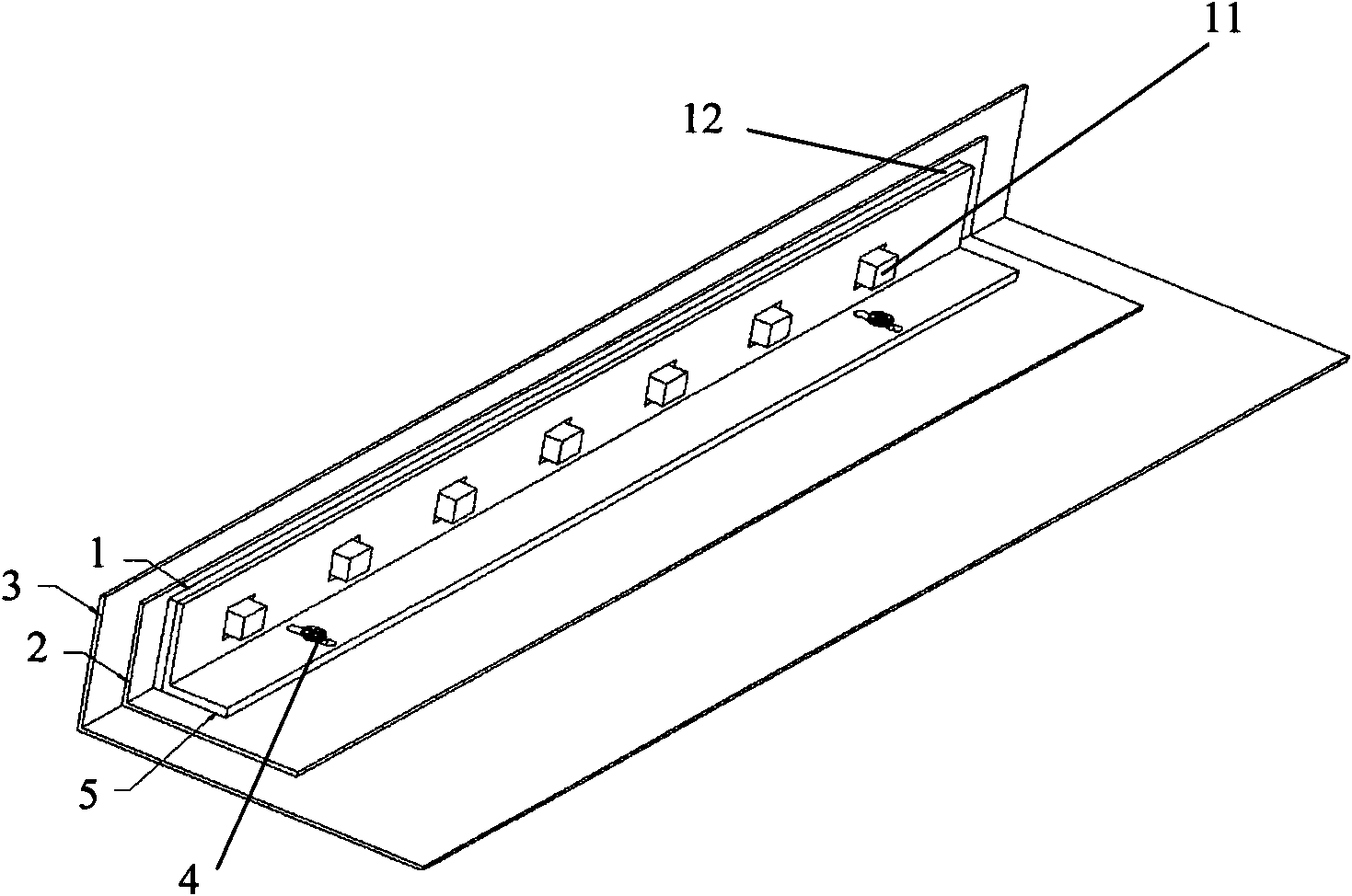
[0024] see Figure 2a and 2b , the first embodiment of the fixing structure of the LED light bar in the backlight module of the present invention generally includes: the LED light bar 1 , the cooling block 2 , the back plate 3 , the fastener 4 and the block 5 . in,

[0025] The LED light bar 1 includes a printed circuit board 12 and several LEDs 11 evenly arranged on the prin...


PUM


Abstract

The invention discloses a liquid crystal display and a backlight module thereof. The backlight module comprises an LED (light emitting diode) light bar, a heat radiation block, a back plate and a stop dog; the LED light bar is fixed on the heat radiation block through a fastening piece; the heat radiation block is fixed on the back plate; and the LED light bar is fixed on the heat radiation blockthrough penetrating the fastening piece on the stop dog. According to the invention, through the cooperation of the stop dog and the heat radiation block, the LED light bar can be conveniently fixed on the heat radiation block, thus the fixed mounting of the LED light bar is realized with lower cost on the premises of ensuring the backlight effect.

Description

technical field [0001] The invention relates to a liquid crystal display device, in particular to the structure of a backlight module in the liquid crystal display device. Background technique [0002] A liquid crystal display device uses liquid crystals to provide image display, and is usually composed of a liquid crystal panel, a backlight module, related digital circuits, and a power supply. Classified by the position of the lamp tube, the backlight module can be mainly divided into three categories: 1. Side-light structure, the light source is set on the side of the light guide plate; 2. Direct-down structure, the light is emitted by the spontaneous light source through the reflector After reflection, it is evenly dispersed upwards through the diffusion plate and then emitted from the front; 3. Hollow structure, using hot cathode tubes as the light source, this structure uses air as the light medium, and the light source is adjusted and reflected downward by the prism sh...

Claims


Application Information

Patent Timeline
Patent Type & Authority Applications(China)
IPC IPC(8): F21S8/00F21V19/00G02F1/13357F21Y101/02
CPCG02B6/0085G02B6/009G02F1/133615G02F1/133628
Inventor 梁硕珍
Owner TCL CHINA STAR OPTOELECTRONICS TECH CO LTD
Why Eureka
Try Eureka