Compound combustion boiler

A boiler and furnace technology, applied in the field of composite combustion boilers

Active Publication Date: 2012-02-15
海宁市袁花镇工业投资有限公司
View PDF5 Cites 8 Cited by
  • Summary
  • Abstract
  • Description
  • Claims
  • Application Information

AI Technical Summary

Problems solved by technology

[0003] The present invention is proposed in view of the above problems, in order to provide a new type of composite combustion boiler, which can make the flue gas and dust after the primary combustion enter the composite furnace, and use the high temperature waste heat of the composite furnace to carry out secondary combustion with air. No pollution discharge, especially solve the world problem of no pollution discharge in waste incineration power generation

Method used


Image

  • Compound combustion boiler
  • Compound combustion boiler
  • Compound combustion boiler

Examples


Embodiment approach 1

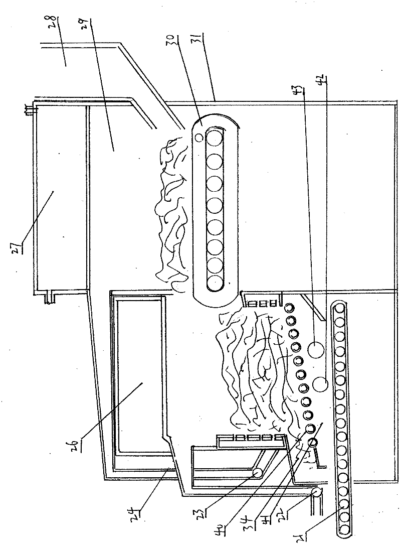
[0038] Such as figure 1 The composite combustion boiler shown in the first embodiment of the present invention includes a boiler 31 and a composite furnace 24. The fuel is sent to the fire grate 30 in the combustion chamber 29 of the boiler through a feeding device 28 for combustion, and then passed through a box-type heat collector. 27 produces hot water or steam, and the burnt slag is discharged from the boiler 31 through the fire grate 30 and enters the rotary grate 40 of the composite furnace 24 for combustion, and then produces hot water or steam through the box-type heat collector 26, and the fuel in the boiler 31 The smoke and dust discharged during combustion are introduced into the smoke return chamber 41 of the compound furnace 24 through the return smoke fan 23 and the return smoke port 42, mixed with the air pressed in by the fan through the air inlet 43, and passed through the rotating furnace bar 40 in a higher furnace. The secondary combustion is carried out in ...

Embodiment approach 2

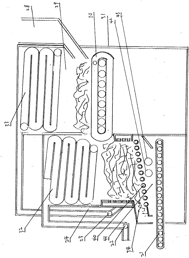
[0041] Such as figure 1 The composite combustion boiler shown in the first embodiment of the present invention includes a boiler 31 and a composite furnace 24. The fuel is sent to the fire grate 30 in the combustion chamber 29 of the boiler through a feeding device 28 for combustion, and then passed through a tubular heat collector 33 Hot water or steam is produced, and the burned slag is discharged from the boiler 31 through the fire grate 30 and enters the rotary grate 40 of the composite furnace 24 for combustion, and then the hot water or steam is produced through the tubular heat collector 32, and the fuel in the boiler 31 is burned The flue dust discharged during the time is passed through the smoke return fan 23, and the smoke return port 42 is introduced into the smoke return chamber 41 of the composite furnace 24, mixed with the air pressed in by the fan through the air inlet 43, and passed through the rotary furnace bar 40 at a higher furnace temperature. The seconda...

Embodiment approach 3

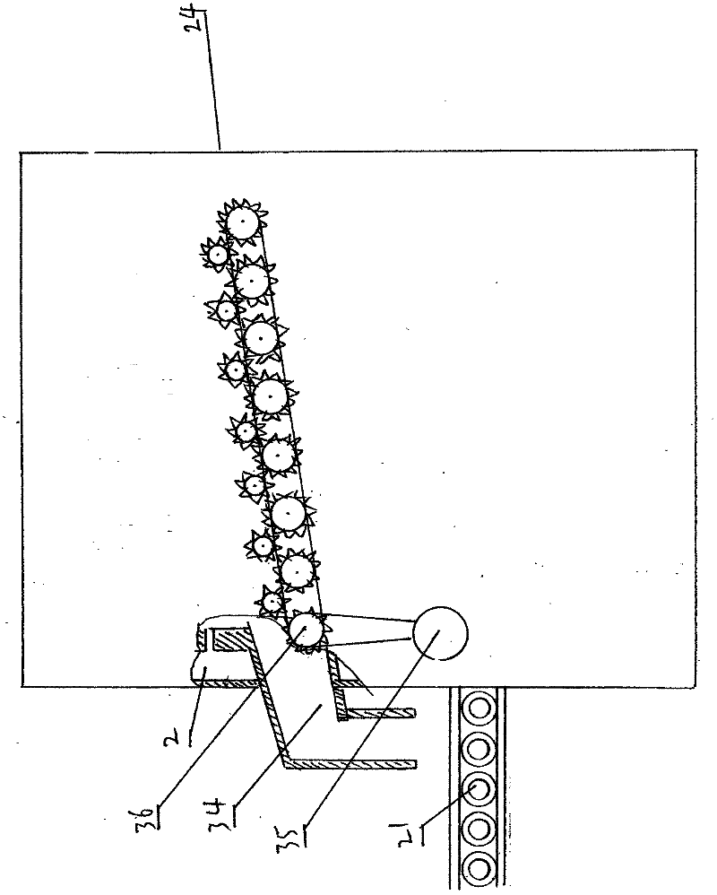
[0044] Such as image 3 The composite combustion boiler according to the third embodiment of the present invention includes a composite furnace 24, a transmission motor 35, a transmission device 36, a coarse slag discharge port 34, and a slag discharge device 21. After the slag is further burned in the composite furnace 24, it passes through the transmission motor 35 Drive the transmission device 36 to rotate, thereby driving the rotating furnace bar to rotate and discharge the slag out of the composite furnace 24, wherein the slag with smaller particles directly falls from the gap between the rotating furnace bars, and the larger pieces of slag are rotated to the coarse slag discharge port through the rotating furnace bar 34 is discharged to the slagging device 21 for discharge.

[0045] According to the above structure, due to the limited space between the rotating bars, it is impossible for large pieces of slag to fall from the space between the rotating bars. By opening th...


PUM


Abstract

The invention provides a compound combustion boiler. By the boiler, fuel is fully combusted, pollution emission is avoided, and energy is saved and consumption is reduced in the using process; and the boiler is provided with at least one three-dimensional hearth and at least one directional combustion-supporting air-cooled revolving grate hearth, and is characterized in that: a slag discharging outlet of the boiler is provided with a directional combustion-supporting air-cooled revolving grate compound hearth with an assembly slag discharging plate or slag discharging teeth; a revolving grate is arranged at the bottom of the compound hearth; the outer end of the revolving grate is assembled with the slag discharging plate or slag discharging teeth; a flue gas return chamber is formed below the grate; a flue gas return fan is arranged outside the flue gas return chamber; a fan is arranged outside the compound hearth; and flue gas discharged by the boiler circularly enters the flue gas return chamber at the bottom of the directional combustion-supporting air-cooled revolving grate compound hearth through the flue gas return fan, and is mixed with air, subjected to secondary combustion by the boiler at high temperature, and discharged into the atmosphere through a flue gas discharging pipe, a flue gas discharging fan and a flue gas discharging chimney.

Description

Technical field: [0001] The invention relates to a composite combustion boiler, which is used for steam and hot water production in industrial production and civil heating. Background technique: [0002] At present, all boilers use single furnace and grate technology. In use, the flue gas still cannot carry out fundamental secondary combustion. Although some boilers have added dust removal and sulfur removal devices, there are still A large number of combustible gases and particles not only cause environmental pollution, waste resources, but also increase production costs. The exhausted flue gas must be treated by special equipment, so the efficiency is very low, environmental pollution, and waste of resources are very serious. Invention content: [0003] The present invention is proposed in view of the above problems, in order to provide a new type of composite combustion boiler, which can make the flue gas and dust after the primary combustion enter the composite furnace...

Claims


Application Information

Patent Timeline
Patent Type & Authority Applications(China)
IPC IPC(8): F23B30/10F23B80/02F23H9/00F23H15/00
CPCF23B30/10F23B80/02F23H9/00F23H15/00
Inventor 李仕清
Owner 海宁市袁花镇工业投资有限公司
Why Eureka
Try Eureka