Refrigeration system with low energy consumption and using method thereof

A refrigeration system and refrigerant technology, which is applied in the direction of refrigerators, refrigeration components, refrigeration and liquefaction, etc., can solve the problems of increased energy consumption, energy consumption, and the inability to realize Carnot reverse cycle, etc., and achieve the effect of energy consumption reduction

Active Publication Date: 2012-02-15
卓卫民
View PDF7 Cites 5 Cited by
  • Summary
  • Abstract
  • Description
  • Claims
  • Application Information

AI Technical Summary

Problems solved by technology

[0010] For this reason, the technical problem to be solved by the present invention is that in the prior art, when the indoor ambient temperature is higher than the outdoor ambient temperature and the heat needs to be released from the indoor environment to the outside, if the circulation device of the Carnot reverse cycle is used and the P1 is greater than The advantage of P2 does not require the compressor to do work, so the Carnot reverse cycle cannot be realized; when the compressor is used to perform work to realize the smooth progress of the Carnot reverse cycle, the energy consumption of the compressor increases due to the power consumption of the compressor, thereby providing an in- In the above-mentioned working conditions where the indoor ambient temperature is higher than the outdoor ambient temperature and heat needs to be released from the indoor ambient temperature to the outdoors, that is, the energy cycle system that does not need to use the compressor to do work and can also release the indoor ambient heat to the outdoor environment

Method used


Image

  • Refrigeration system with low energy consumption and using method thereof
  • Refrigeration system with low energy consumption and using method thereof
  • Refrigeration system with low energy consumption and using method thereof

Examples


Embodiment Construction

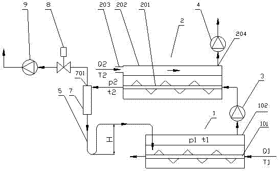
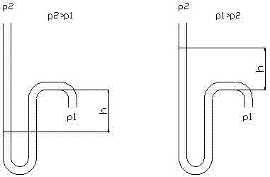
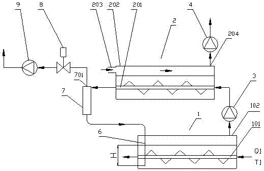
[0038] Such as figure 1 As shown, the refrigeration system of the present invention includes an evaporator 1, the pressure of the refrigerant in the evaporator 1 is p1, and the temperature is t1; a condenser 2, the pressure of the refrigerant in the condenser 2 is p2, the temperature is t2; the setting position of the condenser 2 is higher than the setting position of the evaporator 1; the compressor 3, the inlet end of the compressor 3 is connected to the evaporator 1, and the outlet end is connected to the The condenser 2; also includes a U-shaped tube 5 for connecting the evaporator 1 and the condenser 2, the height H of the U-shaped tube 5 satisfies ρgH>p2-p1, where ρ is the density of the refrigerant. In this embodiment, the evaporator 1 includes an evaporator box 102, the evaporator box 102 contains refrigerant, and the bottom of the evaporator box 102 is arranged with a first heat exchanger plate through which the cooling air passes. tube 101, the first heat exchanger ...


PUM


Abstract

The invention relates to a refrigeration system. The refrigeration system comprises an evaporator, a condenser, a compressor and a U-shaped tube or a straight tube, wherein the mounting position of the condenser is higher than that of the evaporator; and the height H of the U-shaped tube or the depth H that the straight tube is inserted below the liquid level of a refrigerant in the evaporator accords with a formula of rho gH>p2-p1, wherein rho is the density of the refrigerant. For a condition that indoor temperature T1 is lower than outdoor temperature T2, the refrigeration system adopts Carnot reverse cycle; and for a condition that the indoor temperature T1 is higher than the outdoor temperature T2, the refrigeration system adopts Carnot cycle, p2<p1, at the moment, refrigerant steam pushes the compressor to idle, and the refrigerant in the U-shaped tube or the straight pipe completes constant entropy compression by means of self gravity without energy consumption, so that the energy consumption of the system is extremely low. The refrigeration system can use other liquid with the boiling point between 20 and 100 DEG C, such as methanol, ethanol and the like as the refrigerant.

Description

technical field [0001] The invention belongs to the technical field of air conditioning and refrigeration, and in particular relates to a refrigeration system and an application method thereof. Background technique [0002] At present, the refrigeration cycle technology mainly adopts the Carnot reverse cycle, which consists of four cycle processes: isothermal evaporation of refrigerant, constant entropy compression of refrigerant vapor, isothermal condensation of refrigerant and constant entropy expansion of refrigerant liquid. Correspondingly, air-conditioning refrigeration equipment is mainly composed of four components: evaporator, compressor, condenser, and capillary expansion valve. The current refrigeration technology is mainly to transfer heat from a low-temperature heat source with a temperature of T1 to a high-temperature heat source with a temperature of T2, that is, to transfer heat from a cold source to a heat source, commonly known as a "heat pump". [0003] Fo...

Claims


Application Information

Patent Timeline
Patent Type & Authority Applications(China)
IPC IPC(8): F25B13/00F25B39/02F25B39/04
Inventor 卓卫民
Owner 卓卫民
Why Eureka
Try Eureka