Pipe-end induction-based magnetic particle flaw detector

A technology of induction magnetism and flaw detection machine, applied in the direction of material magnetic variable, etc., can solve problems such as complex structure, large machine shape, uneven magnetic field, etc., and achieve the effect of high sensitivity, small machine shape, and no blind zone in the magnetic field

Active Publication Date: 2012-02-15
SHEYANG ZHINENG DETECTING EQUIP
View PDF7 Cites 8 Cited by
  • Summary
  • Abstract
  • Description
  • Claims
  • Application Information

AI Technical Summary

Problems solved by technology

[0003] At present, there is no testing equipment for simultaneous magnetic particle flaw detection on the inner and outer walls of the pipe end. The traditional pipe end magnetic particle flaw detector cannot make the tubular workpiece subject to longitudinal magnetization and circumferential magnetization in one state at the same time, and the magnetic field generated by this method is not uniform. , so that there is an inspection blind spot on the tubular workpiece; although the Chinese patent (publication number is CN1157281) with the patent number ZL200820031993.9 disclosed a composite magnetization flaw detection device inside and outside the pipe end on January 7, 2009 and the patent number is 200810020444.6 The Chinese patent on March 7, 2009 disclosed a composite magnetization flaw detection device inside and outside the pipe end, which can make the workpiece under test obtain stable and uniform axial and circumferential magnetic fields in the same state, but the whole machine is huge , its structure is more complex

Method used


Image

  • Pipe-end induction-based magnetic particle flaw detector
  • Pipe-end induction-based magnetic particle flaw detector
  • Pipe-end induction-based magnetic particle flaw detector

Examples


Embodiment Construction

[0020] Describe the present invention in detail below in conjunction with accompanying drawing:

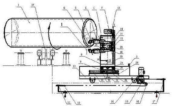
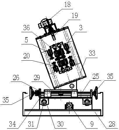
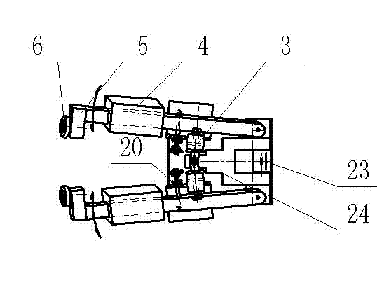
[0021] Such as Figure 1-3 As shown, the pipe end induction magnetic particle flaw detection machine includes the electrical control system, spraying system, circumferential magnetization power supply, longitudinal magnetization power supply, lighting device, auxiliary device for entering and exiting the large oil pipe workpiece 1 to be detected, and the driving workpiece support used in the prior art. The roller 27 drives the rotating device of the detected large-scale oil pipe workpiece 1; it also includes a mobile reducer 14, a traction chain tension frame 12, a traction chain 13, a driving sprocket 15, and a driven sprocket for the fast movement of the drive frame 10. 16. Chain tensioning bolts 17; the magnetic suspension liquid collecting tank 2 is arranged on the top of the frame 10; the magnetic suspension liquid collecting tank 2 is equipped with a lower frame 28, and the ...


PUM


Abstract

The invention relates to a pipe-end induction-based magnetic particle flaw detector. The pipe-end induction-based magnetic particle flaw detector is characterized in that the bottom of a magnetic yoke support is fixed on two inclined support plates of an upper support; a device enabling the magnetic yoke support to move to the front, the back, the left or the right is arranged under the upper support; a speed reducer is arranged at the top of the magnetic yoke support; an output end of the speed reducer is connected to the top of a screw; a nut arranged at a right side surface of a ram is connected to the screw; a left side surface of the ram is fixed with a magnetic yoke bridge; a front side surface and a back side surface of the magnetic yoke bridge are fixed respectively with two pairs of rotatable upper and lower magnetic yoke arms, and two cylinder racks; a right angle-shaped magnetic yoke probe is arranged at another end of each one pair of the rotatable upper and lower magnetic yoke arms; each one of the rotatable upper and lower magnetic yoke arms is provided with a magnetic yoke coil; each one of the two cylinder racks is provided with a magnetic yoke retractable cylinder piston rod; and extension ends of the magnetic yoke retractable cylinder piston rods are connected respectively with the rotatable upper and lower magnetic yoke arms. The pipe-end induction-based magnetic particle flaw detector adopts a compositely rotary magnetization device, and thus making a tubular workpiece needing to be tested have a stable, uniform and high-intensity longitudinal magnetic field and a circular magnetic field in the same state.

Description

[0001] Technical field: [0002] The invention relates to a non-destructive testing machine, in particular to a pipe end induction magnetic powder flaw detector. Background technique [0003] At present, there is no testing equipment for simultaneous magnetic particle flaw detection on the inner and outer walls of the pipe end. The traditional pipe end magnetic particle flaw detector cannot make the tubular workpiece subject to longitudinal magnetization and circumferential magnetization in one state at the same time, and the magnetic field generated by this method is not uniform. , so that there is an inspection blind spot on the tubular workpiece; although the Chinese patent (publication number is CN1157281) with the patent number ZL200820031993.9 disclosed a composite magnetization flaw detection device inside and outside the pipe end on January 7, 2009 and the patent number is 200810020444.6 The Chinese patent on March 7, 2009 disclosed a composite magnetization flaw det...

Claims


Application Information

Patent Timeline
Patent Type & Authority Applications(China)
IPC IPC(8): G01N27/84
Inventor 孙仲义王枫黄建生蒋凤阳
Owner SHEYANG ZHINENG DETECTING EQUIP
Why Eureka
Try Eureka