Distributed Bragg reflector (DBR)-based external cavity wavelength-tunable laser

A technology for tuning lasers and wavelengths, applied to lasers, laser components, semiconductor lasers, etc., can solve problems such as narrow tunable range

Inactive Publication Date: 2012-02-15
李若林 +1
View PDF5 Cites 15 Cited by
  • Summary
  • Abstract
  • Description
  • Claims
  • Application Information

AI Technical Summary

Problems solved by technology

[0005] However, the representative of the traditional tunable laser scheme is the distributed Bragg reflector (DBR) laser, which is characterized in that the active region generating gain and the DBR region generating reflection are formed in the same laser element, and the active gain region is used to pass Electro-optic conversion generates broadband spontaneous emission photons near a certain central wavelength; the reflective grating region is used to selectively reflect photons of specific wavelengths back to the active waveguide region; but its tunable range is very narrow, generally no more than 10nm

Method used


Image

  • Distributed Bragg reflector (DBR)-based external cavity wavelength-tunable laser
  • Distributed Bragg reflector (DBR)-based external cavity wavelength-tunable laser
  • Distributed Bragg reflector (DBR)-based external cavity wavelength-tunable laser

Examples


Embodiment 1

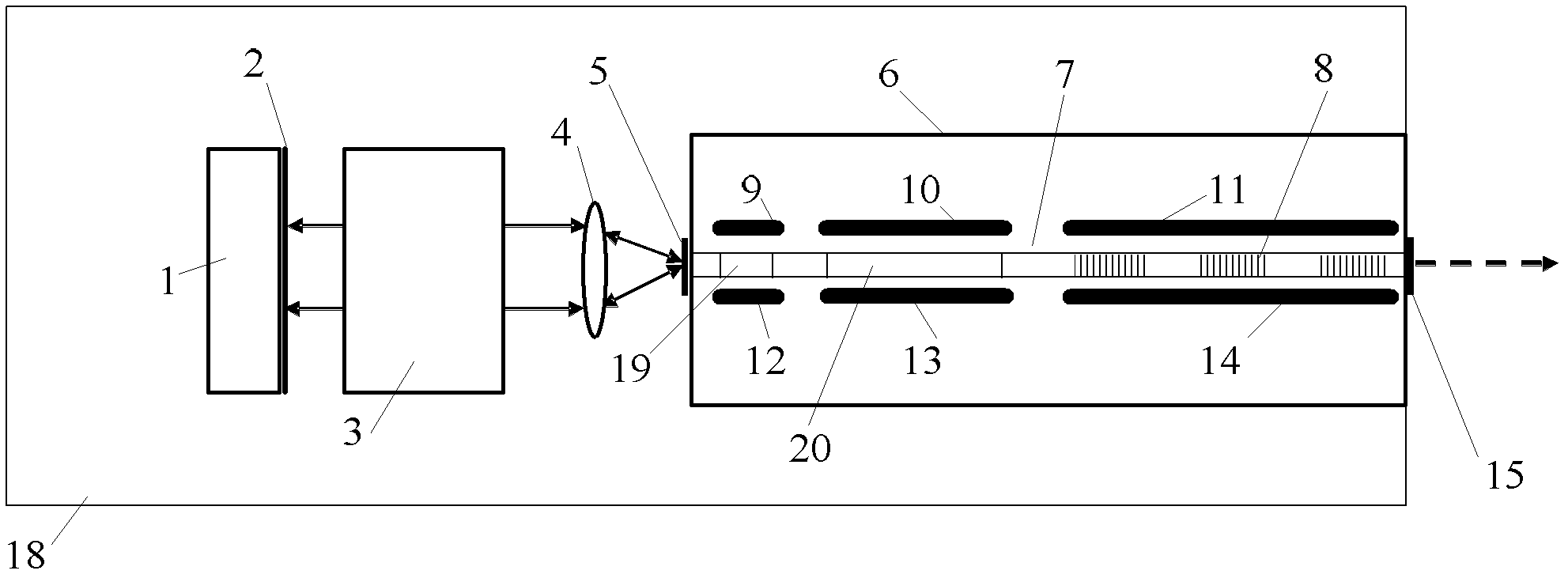
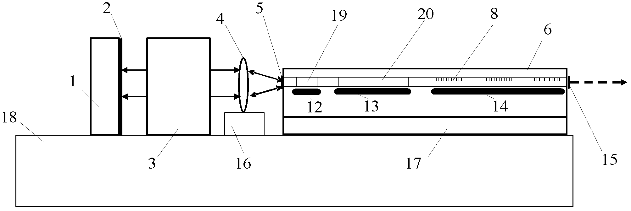
[0032] As shown in Figure 1, a DBR-based external cavity wavelength tunable laser, which includes an active photonic chip 6 for providing an excitation light source, the active photonic chip 6 has an optical waveguide 7, commonly used III-V compound Made of semiconductor material InP series. The optical waveguide 7 includes three sections of a phase area 19, a gain area 20 and a reflective grating area 8, and each section on the optical waveguide 7 is provided with a corresponding electrode, including electrodes 9, 12 placed on the phase area 19, The electrodes 10, 13 placed on the gain region 20, the electrodes 11, 14 placed in the reflection grating region 8; the two ends of the optical waveguide 7 are coated with anti-reflection films 5, 15; On one side of the port 5, an optical lens 4 for beam expansion and collimation, an optical etalon 3 for generating a comb-shaped transmission peak distribution, and a mirror 2 are sequentially arranged, and the mirror 2 is a mirror wit...

specific Embodiment 2

[0045] Such as Figure 3a , 3b Shown is the specific embodiment 2 of the present invention, and the process of forming the laser resonant cavity and generating laser is all the same in this embodiment 2 and embodiment 1, and the difference with embodiment 1 is: the optical etalon 3 is also provided with on the heated electrodes 31,32. The heating electrodes 31, 32 can be made on the surface of the optical etalon 3 around the optical aperture of the light beam, and the refractive index of the optical etalon 3 can also be changed by heating the electrodes 31, 32, so that the comb-like shape of the optical etalon 3 can be made The transmission peak distribution also changes accordingly.

[0046] First change the wavelength position of the comb-shaped maximum reflection peak distribution in the reflection grating area through the corresponding local electrodes, or first change the wavelength position of the comb-shaped maximum transmission peak distribution of the optical etalon...


PUM


Abstract

The invention discloses a distributed Bragg reflector (DBR)-based external cavity wavelength-tunable laser, which comprises an active photonic chip. An optical waveguide is arranged in the photonic chip, and comprises a gain section and a reflection grating section. The two sides of each section are provided with a corresponding electrode respectively. An optical lens, an optical etalon and a reflector are sequentially arranged on one side an optical waveguide port from which the emitted light of a reflection grating is derived, and form a passive external cavity feedback area which forms a laser resonant cavity with the photonic chip. Photons obtain maximum feedback at an overlapped wavelength by changing the comb maximum reflection peak distribution of the reflection grating section or simultaneously changing the comb maximum reflection peak distribution and the maximum transmission peak distribution of the optical etalon to realize the stepped or continuous tuning of output laser wavelengths and changing the output laser wavelengths within a relatively wider range.

Description

technical field [0001] The invention relates to a semiconductor laser, in particular to a DBR-based external cavity wavelength tunable laser. Background technique [0002] Wavelength Division Multiplexing (WDM) has been widely used in optical fiber communication systems. A wavelength division multiplexed optoelectronic transponder consists of a laser, a modulator, a receiver and associated electronics. The operation of the WDM converter can be realized by a fixed-wavelength laser at the near-infrared wavelength of 1550nm. Due to the ease of operation and high reliability, distributed feedback (DFB) lasers are widely used in WDM transmission systems. In the DFB laser, the diffraction grating that provides optical feedback is located above the entire gain resonant cavity, so that the laser will obtain a stable single-mode oscillation at a fixed wavelength. Moreover, information transmission at low digital rates can also be achieved by directly modulating DFB lasers. [000...

Claims


Application Information

Patent Timeline
Patent Type & Authority Applications(China)
IPC IPC(8): H01S5/125H01S5/14
Inventor 李若林
Owner 李若林
Why Eureka
Try Eureka