Combined filling mold

A technology for filling molds and components, which is applied in the direction of formwork/formwork/work frame, building components, and on-site preparation of building components to achieve the effects of reducing production costs, reducing transportation losses, and reducing transportation costs

Inactive Publication Date: 2012-02-22
谢孟
View PDF7 Cites 5 Cited by
  • Summary
  • Abstract
  • Description
  • Claims
  • Application Information

AI Technical Summary

Problems solved by technology

[0003] The technical problem to be solved by the present invention is to overcome the deficiencies of the above-mentioned existing various filling molds. The present invention provides a new composite filling mold of thin-walled components assembled on site and connected to each other. The components of the composite filling mold of the present invention are plate structures It is convenient for factory batch production, which is conducive to improving production efficiency and reducing production costs, and is conducive to sufficient transportation to reduce transportation costs. Due to its light weight, it is convenient for manual loading and unloading and installation, which is conducive to reducing construction and installation costs. Diversified requirements not only make up for the shortcomings of various filling molds, but also have low cost and simple operation

Method used


Image

  • Combined filling mold
  • Combined filling mold
  • Combined filling mold

Examples


Embodiment 1

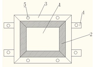
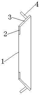
[0043] Embodiment 1:: the present invention adopts the thin-walled member of plastic material casting production standard in the factory, and thickness is 5mm, and panel 1 adopts concave-convex rectangular hemp panel, and size is two kinds of A:600x600mm and B:600x300mm, and panel 1 is connected around The stiffener, the width of the stiffener 2 is 50mm, the outer surface of the stiffener is also concave-convex, and the stiffener 2 is 45mm from the panel 1. o angle, the stiffening plate 2 is connected with the counter force plate 3 around, the width of the counter force plate 3 is 30mm, and the reaction force plate 3 is connected with the end of the stiffening plate 2, forming a 90 o Angle, two reaction force keys 4 are set on the reaction force plate in the left and right directions, the width of the reaction force keys 4 is 30mm, and a connection hole with a diameter of 10mm is set on the reaction force keys 4. After the standard components are transported to the constructio...

Embodiment 2

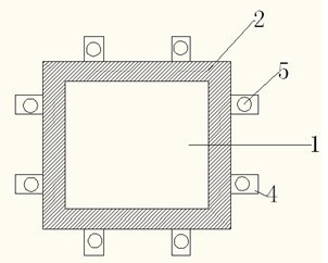
[0044] Embodiment 2:: the present invention adopts plastic material to cast and press the thin-walled member of production standard in factory, and thickness is 5mm, and panel 1 adopts concave-convex rectangular hemp panel, and size is two kinds of A: 600x600mm and B: 600x300mm, and panel is connected and stiffened around Plate 2, the width of the stiffener plate is 50mm, the outer surface of the stiffener plate 2 is also concave-convex, and the stiffener plate and the face plate are 60 o Included angle, two reaction keys are connected in each direction around the stiffening plate, the width of the reaction key is 30mm, and each reaction key is provided with a connecting hole with a diameter of 10mm. After the standard components are transported to the construction site, support the bottom formwork according to the design requirements, bind the bottom reinforcement and rib inner steel bars on the bottom formwork according to the design requirements, place the A-shaped component...


PUM


Abstract

The invention discloses a combined filling mold. The mold is enclosed by a thin wall plate type member, wherein the thin wall plate type member comprises a panel (1), a stiffening plate (2), a counter force plate (3) or a counter force key (4); the periphery of the panel (1) is connected with the stiffening plate (2); the periphery of the stiffening plate (2) is connected with the counter force plate (3) or the counter force key (4); and at least one connecting hole (5) is formed in the counter force key (4). Novel filling mold combination members which are assembled on site and are connected with one another are convenient for industrial mass production, contribute to improvement on production efficiency and reduction in production cost and contribute to sufficient quantity transportation and reduction in transportation cost; because of light weight, the mold can be conveniently assembled, disassembled and mounted manually and contributes to reduction in construction and mounting cost; and due to the adoption of a combined structure, requirements on product diversification are convenient to meet, the defects of the conventional various filling molds are overcome, and the mold has low cost and is easy to operate.

Description

technical field [0001] The invention relates to a formwork for building floors, in particular to a combined filling form. Background technique [0002] There are more and more empty-web reinforced concrete floor slab structures using filling internal formwork construction technology. The characteristics of the empty-web slab are large cross-sectional height, internal void, concrete thin slabs on the upper and lower sides, and concrete mesh-like concrete ribs between the upper and lower concrete thin slabs and the filling mold. There are some problems in the existing technology: firstly, the anti-floating problem of the filling mold. The existing various filling molds all use thin walls and cavities to reduce the self-weight load of the floor. In order to prevent the filling mold from floating when the concrete is poured, various Fixing measures, one measure is to use thick steel bars to connect the filling formwork with the steel mesh of the structure, and use the self-weigh...

Claims


Application Information

Patent Timeline
Patent Type & Authority Applications(China)
IPC IPC(8): E04G15/06E04B5/36E04C1/00
Inventor 谢孟
Owner 谢孟
Why Eureka
Try Eureka