
Pressure regulating valve group of pressure regulating cone valve

A technology of pressure regulating valve group and cone valve, which is applied in the field of pressure regulating valve group, can solve the problems of gas personal safety hazards, gas leakage, gas leakage, etc., achieve obvious economic and social benefits, reduce direct scouring wear, prolong The effect of service life

Active Publication Date: 2012-02-22
SHIJIAZHUANG SHITE VALVE
View PDF8 Cites 6 Cited by
  • Summary
  • Abstract
  • Description
  • Claims
  • Application Information

AI Technical Summary

Problems solved by technology

at 2500m 3 Take a volumetric blast furnace as an example. In actual production, the resonance amplitude of the pipeline system near the butterfly valve pressure regulating valve group can reach 40-50mm. Gas leaks from nearby pipelines and blast furnaces are forced to shut down
The turbulent flow of the gas quickly washes the inner wall and valve seat of the valve body with fine dust particles, and the valve body will be worn out within 3-6 months, resulting in gas leakage and shutdown of the blast furnace. The leaked gas is harmful to personal safety, and the strong noise is serious. Affect people's work and life
Therefore, if the traditional butterfly valve pressure regulating valve group is used as the pressure regulating equipment, the rapid erosion of the inner wall of the valve by the air flow, the severe vibration of the pipeline and the strong noise are unavoidable

Method used


Image

  • Pressure regulating valve group of pressure regulating cone valve
  • Pressure regulating valve group of pressure regulating cone valve
  • Pressure regulating valve group of pressure regulating cone valve

Examples


Embodiment Construction

[0018] The present invention is described in detail below in conjunction with embodiment with accompanying drawing:

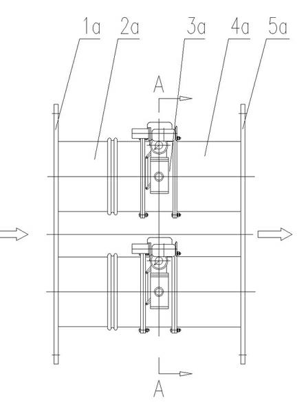
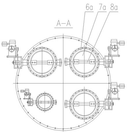
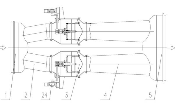
[0019] Such as image 3 As shown, the pressure regulating cone valve pressure regulating valve group of the present invention includes a front pipe 1, a front guide pipe 2, a pressure regulating cone valve 3, a rear guide cone pipe 4, and a rear pipe 5, wherein at least two front pipes are connected to the front pipe 1. The guide pipe 2 is evenly distributed along the center of the front pipe 1, and the other end of each front guide pipe 2 is connected to a pressure-regulating cone valve 3 through a flange connection. The other end of each pressure-regulating cone valve 3 A rear guide tapered pipe 4 is respectively connected by a flange connection type, and all rear guide tapered pipes 4 are connected with the rear pipe 5 and are evenly distributed along the equidistant circumference of the pipe center of the rear pipe 5 . The number of the front guide pipe 2,...


PUM


Abstract

The invention relates to pressure regulating valve group equipment which controls top gas pressure of an iron making blast furnace and can control the top pressure of the blast furnace in a range required by an iron making process. The equipment comprises a front pipe, a front guide pipe, a pressure regulating cone valve, a rear guide cone pipe and a rear pipe, wherein a guide cylinder is arranged in a shell of the pressure regulating cone valve; a valve flap is arranged in the guide cylinder and provided with a sealing ring; a flow guide plate is arranged in the shell and connected with a valve seat; sealing surfaces which are mutually matched are arranged between the valve flap and the valve seat; the valve flap is connected with a valve rod; a rocker is connected with a transmission shaft through a key; and when a driving device drives the transmission shaft to rotate, the rocker and a connecting rod are driven to rotate, and the valve rod and the valve flap move back and forth, sothat the opening and closing process of the pressure regulating cone valve is operated. The circulation area of gas flow between the valve flap and the valve seat is changed by moving the valve flap back and forth to fulfill the aim of pressure regulating, so that the service life of a pressure regulating valve group can be greatly prolonged, the safe, reliable and high-efficiency production of the blast furnace is ensured, and economic benefits and social benefits are obvious.

Description

technical field [0001] The invention relates to a pressure regulating valve group, in particular to a pressure regulating cone valve pressure regulating valve group equipment for controlling the gas pressure at the top of an ironmaking blast furnace and controlling the top pressure of the blast furnace within the range required by the ironmaking process. Background technique [0002] The pressure regulating valve group is a pressure regulating device that controls the gas pressure at the top of the ironmaking blast furnace. Only by controlling the pressure at the top of the blast furnace within the range required by the ironmaking process can the normal and high-efficiency production of blast furnace ironmaking be guaranteed. With the rapid development of domestic blast furnace ironmaking technology, the volume of blast furnaces is getting larger and larger, requiring higher and higher furnace top pressure, and the ironmaking dust removal technology is changed from wet dust r...

Claims


Application Information

Patent Timeline
Patent Type & Authority Applications(China)
IPC IPC(8): F16K17/20F16K47/02C21B7/00
Inventor 姜亚平袁大为
Owner SHIJIAZHUANG SHITE VALVE
Learn More