Real-time strain measurement apparatus for stamping and forming and test method thereof

A technology of strain measurement and stamping forming, which is applied in the field of real-time strain measurement devices, can solve the problems of non-contact testing methods, embedding sensors, and difficulty in testing, etc., to overcome real-time working condition testing, reduce stamping defects, low cost effect

Inactive Publication Date: 2012-02-22
YANGZHOU UNIV
View PDF0 Cites 10 Cited by
  • Summary
  • Abstract
  • Description
  • Claims
  • Application Information

AI Technical Summary

Problems solved by technology

In the stamping process of the sheet metal, the sheet material at the deformation processing part is just in the pressing area of ​​the upper and lower stamping dies, and the non-contact test method cannot be applied, and the sensor cannot be embedded in the sheet material, so it is necessary to test it under actual working conditions very difficult

Method used


Image

  • Real-time strain measurement apparatus for stamping and forming and test method thereof
  • Real-time strain measurement apparatus for stamping and forming and test method thereof
  • Real-time strain measurement apparatus for stamping and forming and test method thereof

Examples


Embodiment 1

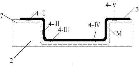
[0018] like figure 1 As shown, the real-time strain measurement device for stamping includes static strain gauge 6, wire 5, strain gauges 4-I, 4-II, 4-III, 4-IV, 4-V and dies, strain gauges 4-I, 4-Ⅱ, 4-Ⅲ, 4-Ⅳ, 4-Ⅴ are fixed on the corresponding test points of the plate 3, and the strain gauges 4-Ⅰ, 4-Ⅱ, 4-Ⅲ, 4-Ⅳ, 4-Ⅴ pass through the wire 5 Connected with the static strain gauge 6, the mold includes a die 1 and a die 2. The position corresponding to the test point of the die 2 is provided with a groove 7 for placing a strain gauge, and the groove 7 is on the front and rear symmetry lines of the die. The strain gauges are placed in the groove 7. The static strain gauge adopts the 1 / 4 bridge method. The strain gauges of all test points are connected to the AB bridge arm of the static strain gauge through wires, and the strain gauges of all test points share a compensation plate connected to the common compensation bridge arm of the static strain gauge.

Embodiment 2

[0020] A real-time strain measurement method for stamping, comprising the following steps:

[0021] (1) Equipped with a real-time strain measurement device for stamping: a mold consisting of static strain gauge 6, wire 5, strain gauges 4-I, 4-II, 4-III, 4-IV, etc., die 1 and die 2, Static strain gauge is 1 / 4 bridge method;

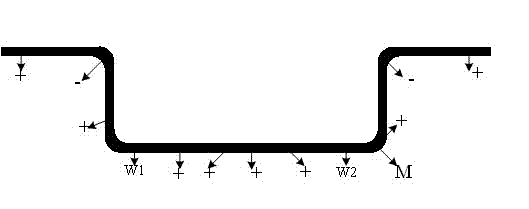
[0022] (2) According to the deformation characteristics of the workpiece, such as figure 2 As shown, in different deformation parts of the workpiece and parts with different strain characteristics, the two sides of the bending angle formed by stretch bending: w1 and w2, and several positions are determined on the surface (M surface) in contact with the die. Test points, paste the strain gauges 4-Ⅰ, 4-Ⅱ, 4-Ⅲ, 4-Ⅳ, 4-Ⅴ on the corresponding test points respectively;

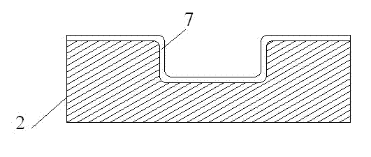
[0023] (3) Process the groove 7 at the position corresponding to the test point determined in step (2) on the die, the position is as follows image 3 As shown, the strain gauge pasted on th...

Embodiment 3

[0026] figure 1 In this embodiment, the present embodiment is used to measure the stress and strain of a blank (workpiece) 3 in real time during the stamping process of a U-shaped piece by a stamping die. In this example, if Figure 4 As shown, five key points (test points) are taken in total on the flange edge of the U-shaped piece, one side close to the bending angle, the straightened wall of the U-shaped piece, and the bottom of the specimen (workpiece); these parts are U-shaped During the forming process of the molded part, the most severe or close to the most severe part of the mold force ensures that the strain is within the applicable range of the strain gauge. In order to ensure that the strain gauge 4 and the wire 5 are not affected by the mold during the stamping process, a groove 7 with a certain width and depth is processed on the position corresponding to the key point of the die 2, and the strain gauge is placed on the groove 7. out of groove 7. The static str...


PUM


Abstract

The invention, which belongs to the dynamic strain measurement technology field, relates to a real-time strain measurement apparatus for stamping and forming and a test method thereof. The real-time strain measurement apparatus comprises a static strain indicator, leads, foil gauges and a die. The foil gauges are fixed on test points and are connected with the static strain indicator through leads; besides, the die comprises a punch die and a female die; and a groove that is used for placing the foil gauges is arranged at positions of the female die, wherein the positions are corresponded to the test points. When real-time strain measurement on stamping and forming is carried out, different deformation portions of a workpiece and portions having different strain characteristics are utilized as test points of a sheet metal; the foil gauges are pasted; the foil gauges of the apparatus and the connecting leads are placed in the groove; the connecting leads are led out by the groove; and on the basis of utilization of a step-by-step stamping method, a real-time stress strain value is measured and obtained. According to the invention, the structure of the apparatus is simple and reasonable; it only needs to improve a die, so costs are low; and the apparatus has strong practicability; besides, the test method is simple and rapid; and during the part stamping stroke, it is convenient to measure a strain value.

Description

technical field [0001] The invention discloses a stamping forming real-time strain measuring device and a testing method, belonging to a dynamic strain measuring device and a testing method. Background technique [0002] The use of high-strength steel plates in automobiles has highlighted the springback of automotive stamping parts. In order to check the strength changes of high-strength steel plates during stamping, a real-time strain measurement device for stamping is needed. At present, the commonly used strain measurement method is static strain measurement. In the stamping process of the sheet metal, the sheet material at the deformation processing part is just in the pressing area of ​​the upper and lower stamping dies, and the non-contact testing method cannot be applied, and the sensor cannot be embedded in the sheet material, so the actual working condition test is carried out Very difficult. Therefore, a new real-time strain measuring device and testing method fo...

Claims


Application Information

Patent Timeline
Patent Type & Authority Applications(China)
IPC IPC(8): G01B21/32
Inventor 陈靖芯张霞李红
Owner YANGZHOU UNIV
Why Eureka
Try Eureka