Tertiary optical detection machine for IC (integrated circuit) strips and operating method thereof

A material strip and optical inspection technology, which is applied in the direction of analyzing materials, conveyor objects, and optical testing for flaws/defects, etc., can solve the problems of inspection efficiency and quality that manual inspection has no obvious advantages, low work efficiency, and high labor intensity.

Active Publication Date: 2012-02-22
SHENZHEN GRAND INNOSYS CORP
View PDF3 Cites 28 Cited by
  • Summary
  • Abstract
  • Description
  • Claims
  • Application Information

AI Technical Summary

Problems solved by technology

The existing detection methods are not only labor-intensive and low in efficiency, but also the quality of detection varies from person to person, making it difficult to guarantee the quality of product detection
[0003] There are also people who have tried to use the camera to obtain the real-time information of the chip gold wire and compare the information of the standard gold wire template stored in the computer to realize the automatic detection of the gold wire, but they have not found a method that allows the camera to clearly and accurately obtain the various parameters of the gold wire. The lighting system and tracking method of this kind of defect have no obvious advantages over manual inspection in terms of efficiency and quality of inspection

Method used


Image

  • Tertiary optical detection machine for IC (integrated circuit) strips and operating method thereof
  • Tertiary optical detection machine for IC (integrated circuit) strips and operating method thereof
  • Tertiary optical detection machine for IC (integrated circuit) strips and operating method thereof

Examples


Embodiment Construction

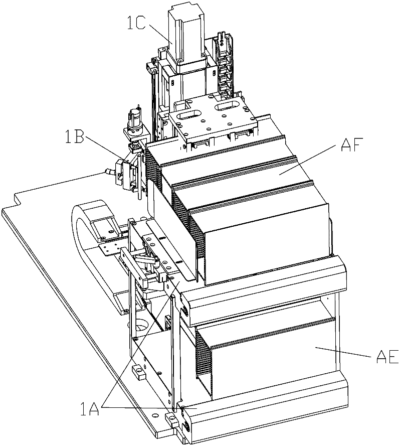
[0037] Commonly used material boxes include trough-type material boxes and stacked-type material boxes. There are slots for inserting strips arranged from top to bottom in the trough-type material boxes. The side and the right side have left and right openings respectively for inserting and extracting strips. The material box that the present invention relates to is above-mentioned trough type material box, and the material box that is equipped with the material strip that waits for light inspection and light inspection is respectively called upper material box and lower material box, in addition, as image 3 As shown, the full-loaded material box waiting for light inspection or the light-inspected strip is called the material box AF, and the empty material box is called the empty material box AE.

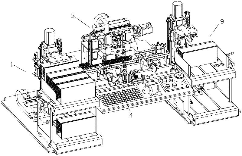
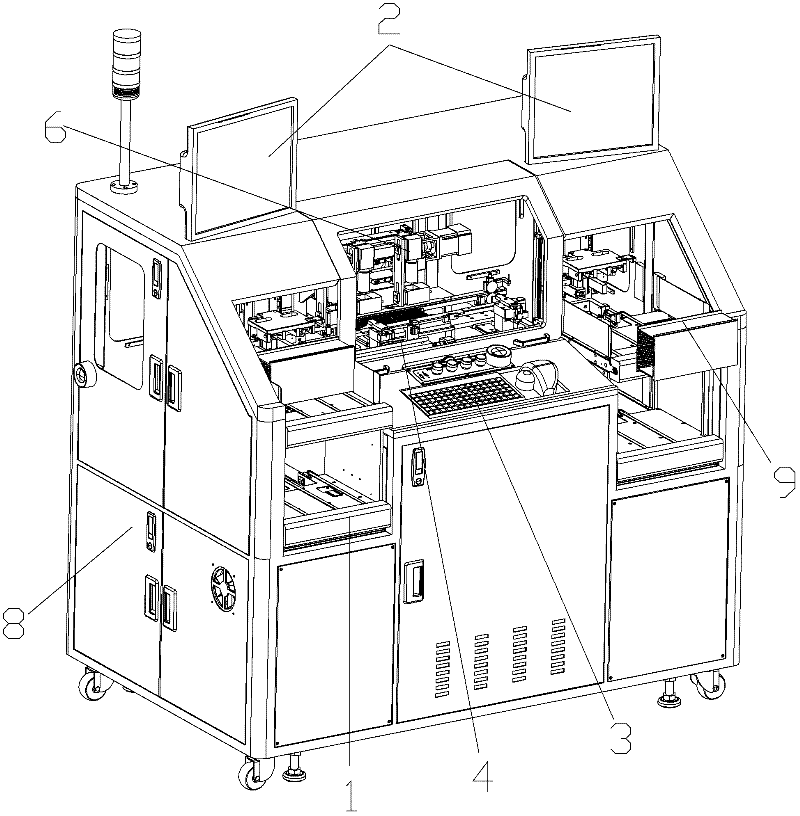
[0038] The three-time optical inspection machine for IC strips of the present invention mainly includes such as figure 1 with 2 Shown strip conveying system 4 and photodetection ...


PUM


Abstract

The invention discloses a tertiary optical detection machine for IC (integrated circuit) strips and an operating method thereof. The tertiary optical detection machine comprises a strip conveying system and an optical detection system. The strip conveying system comprises a strip conveying guide rail, guide rail grooves which are opposite to each other are respectively arranged on a front sectionand a rear section of the strip conveying guide rail, and strips can be inserted into the guide rail grooves from two sides in the length direction. The optical detection system comprises an illumination device and a track moving device, wherein the track moving device is used for driving the illumination device to move in both length and width directions of the strips, and the illumination device comprises a camera and a coaxial light generator below the camera. Besides, the position relation of the coaxial light generator and the camera includes that light emitted from the coaxial light generator and coaxial with a lens of the camera is reflected by the strips and then is emitted to the lens directly through the coaxial light generator. Information of chip wires can be shot through the camera by the aid of the coaxial light generator mounted below the camera, and high-definition pictures can be shot when the track moving device drives the illumination device to move in a high speed.

Description

technical field [0001] The present invention relates to a device for detecting the gold wire of a chip on an IC material strip and its optical detection method, more precisely, it involves capturing and recording the status of the gold wire of a chip on an unmolded material strip one by one A three-time light inspection machine for IC material strips. Background technique [0002] The detection of the gold wire on the chip is the third detection in the chip production process, and the equipment related to the third detection is called the three-time light inspection machine. The detection of gold wires on chips on unmolded strips mainly involves six items: gold wire missing detection, gold wire bending detection, redundant gold wire detection, gold wire short circuit detection, gold wire open circuit detection and gold wire surrounding impurity detection. . At present, the detection content of gold wire is mainly completed by human eye observation detection and manual dete...

Claims


Application Information

Patent Timeline
Patent Type & Authority Applications(China)
IPC IPC(8): G01N21/89G01N21/01B65G47/90
Inventor 林宜龙刘宝龙戚长政唐召来黄水清林清岚王能翔
Owner SHENZHEN GRAND INNOSYS CORP
Why Eureka
Try Eureka