Supercharge Your Innovation With Domain-Expert AI Agents!

Fly-eye lens

A fly-eye lens and micro-lens technology, applied in the direction of lenses, lighting and heating equipment, instruments, etc., can solve the problems of reducing the uniformity of the light field, failing to realize the output light field, and unfavorable utilization of illumination light, so as to improve the light energy Effect of utilization, avoidance of light energy loss and stray light on uniformity

Inactive Publication Date: 2013-11-13
INST OF OPTICS & ELECTRONICS - CHINESE ACAD OF SCI
View PDF4 Cites 1 Cited by
  • Summary
  • Abstract
  • Description
  • Claims
  • Application Information

AI Technical Summary

Problems solved by technology

[0003] The traditional fly-eye lens adopts the same lens group before and after, and most of the fly-eye lenses are glued together to form the whole fly-eye, which cannot realize the trapezoidal distribution of the output light field along the Y-axis in the illumination area, and because each single lens It is formed by bonding, and the gap between the lens units is large. When the light source passes through the front fly-eye lens and irradiates the rear fly-eye lens, part of the light passing through the gap of the single lens cannot be used, which is not conducive to improving the utilization rate of illumination light; The gap between the lenses will cause the loss of stray light, which reduces the uniformity of the light field, and the uniformity can only reach 95% at most; and the shape of the output light field distribution cannot be controlled

Method used


Image

  • Fly-eye lens
  • Fly-eye lens
  • Fly-eye lens

Examples


Embodiment 1

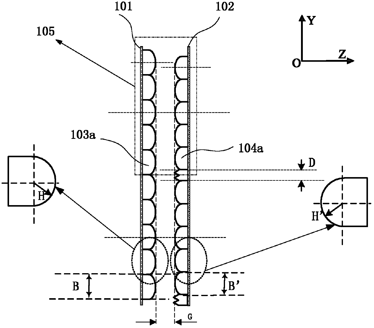
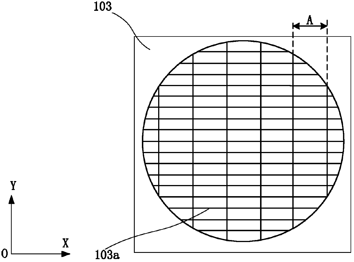
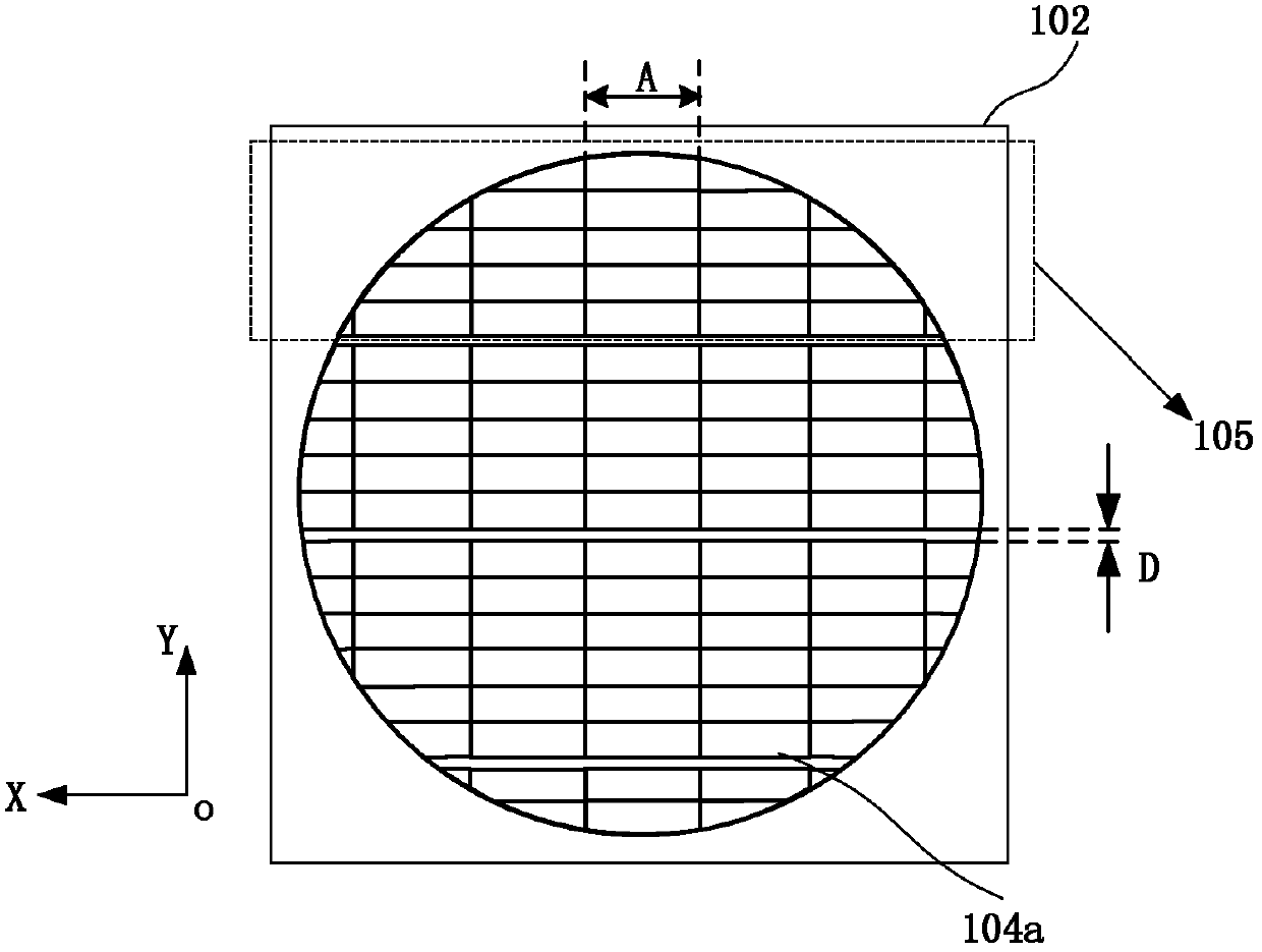
[0029] The fly-eye lens of the present invention comprises front group substrate 101, rear group substrate 102, lens unit group 105 made up of front microlens unit 103a and rear microlens unit 104a, as figure 1 As shown, both the substrate and the microlens unit are made of fused silica; the microlens unit is made by etching the substrate, and the front microlens unit 103a is arranged in an array on one side of the front group substrate 101, as shown in figure 2 As shown, all the microlens units 103a have the same shape and geometric size, and the rear microlens units 104a are arranged in an array at intervals on one side of the rear group substrate 102, as image 3 As shown, the shapes and geometric dimensions of all the front microlens units 103a are the same, and the shapes and geometric dimensions of all the rear microlens units 104a are also the same, and the convex surfaces of the front microlens units 103a and the rear microlens units 104a are placed opposite to each ot...

Embodiment 2

[0040] The structure of the fly eye lens of embodiment two is as figure 2 As shown, the figure includes a substrate 100 , a front microlens unit 103 a , a rear microlens unit 104 a and a lens unit group 105 . Calcium fluoride is used for the base of the fly-eye lens and the materials of the front and rear microlens units. In this embodiment, the front microlens unit 103a and the rear microlens unit 104a are made by etching the two sides of the same substrate 100. The structures and geometric dimensions of the front microlens unit 103a and the rear microlens unit 104a, and the adjacent lens units The calculation method of the gap D of the rear microlens units at the boundary of the group 105 and the offset of the front and rear microlenses, as well as the composition method of the lens unit group 105 are the same as those in Embodiment 1, and will not be repeated here.

Embodiment 3

[0042] Figure 10 It is a structural schematic diagram of a fly-eye lens according to Embodiment 3 of the present invention, including a front group substrate 101, a rear group substrate 102, a front microlens unit 103a, a rear microlens unit 104a and a lens unit group 105, such as Figure 10 As shown, both the substrate and the microlens unit are made of CaF 2 Material; the front microlens unit 103a and the rear microlens unit 104a are relatively placed on the inside of the front group substrate 101 and the rear group substrate 102, the microlens unit is made by etching the substrate, and the front microlens unit 103a is arranged in an array One side of the front group base 101, such as Figure 10 As shown, all the microlens units 103a have the same shape and geometric size, and the rear microlens units 104a are arranged in an array at intervals on one side of the substrate 102, and the shapes and geometric dimensions of the rear microlens units 104a are not all the same. T...


PUM


Abstract

The invention discloses a fly-eye lens which comprises a substrate (100) and a lens unit group (105) arranged on the substrate, wherein the lens unit group (105) is composed of front micro-lens units (103a) and rear micro-lens units (104a) arranged in an array mode, the front micro-lens units (103a) and the rear micro-lens units (104a) are respectively closely connected in an array mode along the directions of an X axis and a Y axis, and the focal distance of each front micro-lens unit (103a) is greater than that of each rear micro-lens unit (104a). The fly-eye lens disclosed by the invention can improve the utilization rate of light energy of a light-equalizing system, and the uniformity of a light field can reach 98%.

Description

technical field [0001] The invention relates to a uniform light optical device used in an illumination system, in particular to a fly-eye lens suitable for the illumination system of a lithography machine. Background technique [0002] A fly eye lens is a whole lens made up of multiple small lenses. It is often used in the illumination optical system to achieve the function of homogenizing the illumination light, and it is the key device to realize the uniformity of the beam. Light beams need to be homogenized in lighting systems such as projection displays and lithography machines. The illumination optical system of the lithography machine mainly requires high light energy utilization rate of the uniform light device and good illumination uniformity, etc. In particular, it is required that the outgoing light is distributed in a trapezoidal shape along the Y axis in the illumination area. [0003] The traditional fly-eye lens adopts the same lens group before and after, an...

Claims


Application Information

Patent Timeline
Patent Type & Authority Patents(China)
IPC IPC(8): G02B27/09G02B3/00G03F7/20F21V5/08
Inventor 廖志杰林妩媚张海波邱传凯
Owner INST OF OPTICS & ELECTRONICS - CHINESE ACAD OF SCI
Features
  • R&D
  • Intellectual Property
  • Life Sciences
  • Materials
  • Tech Scout
  • Unparalleled Data Quality
  • Higher Quality Content
  • 60% Fewer Hallucinations
Learn More