
Finned radiator for transformer

A radiator and transformer technology, applied in the direction of transformer/inductor cooling, etc., can solve the problems of large circulating resistance of transformer oil, low flow rate of transformer oil, unsatisfactory heat dissipation effect of radiator, etc., to improve heat dissipation effect, increase flow rate, easy flow effect

Inactive Publication Date: 2012-02-22
江苏圣塔电力设备有限公司
View PDF6 Cites 5 Cited by
  • Summary
  • Abstract
  • Description
  • Claims
  • Application Information

AI Technical Summary

Problems solved by technology

The two ends of the existing finned radiators have a right-angled small arc transition, the circulation flow resistance of the transformer oil is large, the flow rate of the transformer oil inside the finned radiator is small, and the heat dissipation effect of the radiator is not ideal

Method used


Image

  • Finned radiator for transformer
  • Finned radiator for transformer
  • Finned radiator for transformer

Examples


Embodiment Construction

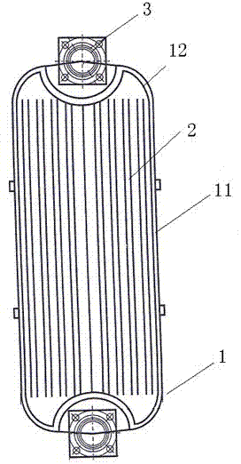
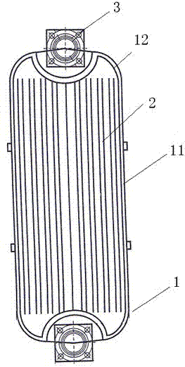
[0013] A kind of sheet radiator for transformer of the present invention, see figure 1 , the fin radiator includes an internal circulating oil passage 1, the internal circulating oil passage 1 includes straight sections 11 on both sides and curved transition sections 12 at four corners, the straight sections 11 are connected by curved transition sections 12, and the curved The transition section 12 is an arc of 200-300 mm. In the figure, 2 is a cooling fin, 3 is a connecting flange, and the connecting flange 3 is connected with the internal circulating oil 1.

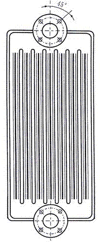
[0014] The present invention improves the internal circulating oil channel of the fin radiator, filters the original small circular arc at the two ends of the single sheet, and changes the design into a large circular arc transition, which makes it easier for the transformer oil to flow in the radiator and reduces the loss of the transformer oil. Circulation flow resistance improves the flow rate of transformer oil in...


PUM

PropertyMeasurementUnit
diameteraaaaaaaaaa

Abstract

The invention discloses a finned radiator for a transformer. The finned radiator comprises an inner oil circulating channel, wherein the inner oil circulating channel comprises linear sections and four curved transitional sections at four corners; the linear sections are connected through the curved transitional sections; and each curved transitional section is in an arc shape. By the finned radiator, the inner oil circulating channel is improved, so the circular flow resistance of transformer oil is reduced, flow speed of the transformer oil in the finned radiator is increased, and the radiating effect of the radiator is improved. The finned radiator for the transformer is particularly applied to high-efficiency and energy-saving oil-immersed transformers with the voltage of 110 to 220KV, and also applied to large power transmission and transformation equipment and direct current power transmission and transformation equipment.

Description

technical field [0001] The invention relates to an oil-immersed transformer, in particular to a sheet radiator for transformers of 110KV and above. Background technique [0002] When the transformer is running, the heat generated by the loss of the winding and core must be dissipated in time to avoid insulation damage caused by overheating. For small-capacity transformers, the ratio of the outer surface area to the volume of the transformer is relatively large, and a self-cooling method can be used to dissipate heat through radiation and natural convection. Since the loss of the transformer is proportional to its volume, as the capacity of the transformer increases, its volume and loss will increase with the cube of the core size, while the external area will only increase with the quadratic of the size. Therefore, the large-capacity transformer core and winding should be immersed in oil, and oil-immersed self-cooling cooling measures should be taken. The vast majority of ...

Claims


Application Information

Patent Timeline
Patent Type & Authority Applications(China)
IPC IPC(8): H01F27/12
Inventor 孙其才
Owner 江苏圣塔电力设备有限公司
Learn More