
Capacitive cross coupling flying bar and coaxial cavity resonator thereof

A cross-coupling and resonator technology, which is applied in the direction of resonators, waveguide devices, electrical components, etc., can solve the problems of large bending angle tolerance, device ignition and burnout, and increase the length of the rod, so as to achieve high installation accuracy and ensure Consistent, reliable connection results

Active Publication Date: 2012-02-22
WUHAN HONGXIN TELECOMM TECH CO LTD
View PDF10 Cites 19 Cited by
  • Summary
  • Abstract
  • Description
  • Claims
  • Application Information

AI Technical Summary

Problems solved by technology

For the integrated flying rod, increasing the coupling plate will greatly increase the cost, generally by increasing the length of the rod; to reduce the distance between the rod and the resonant column to achieve a strong capacitive cross-coupling effect, which may cause high-power signals to pass through the device There will be fire damage
For the sheet-shaped flying rod, it is thin and has two bending parts at the end. The bending angle tolerance in the actual stamping process is relatively large, which will inevitably lead to the bending part being remote or close to the resonant column, and the coupling amount is small when it is remote. , the amount of coupling is too large when it is too close, both of which will lead to poor consistency

Method used


Image

  • Capacitive cross coupling flying bar and coaxial cavity resonator thereof
  • Capacitive cross coupling flying bar and coaxial cavity resonator thereof
  • Capacitive cross coupling flying bar and coaxial cavity resonator thereof

Examples


Embodiment Construction

[0024] Below in conjunction with accompanying drawing and embodiment describe in detail:

[0025] 1. Capacitive cross-coupled fly rod (referred to as coupled fly rod)

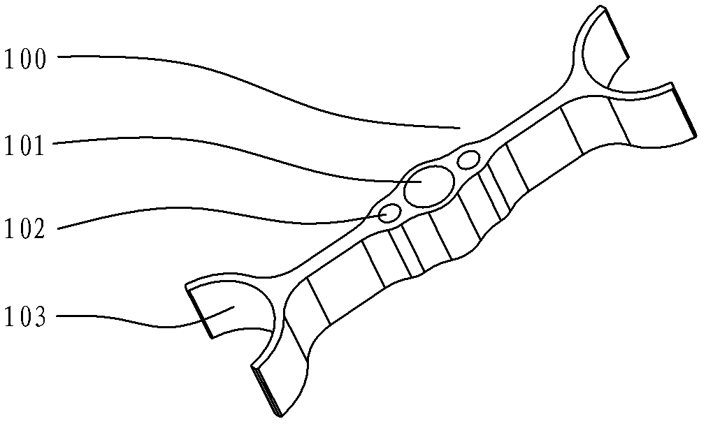
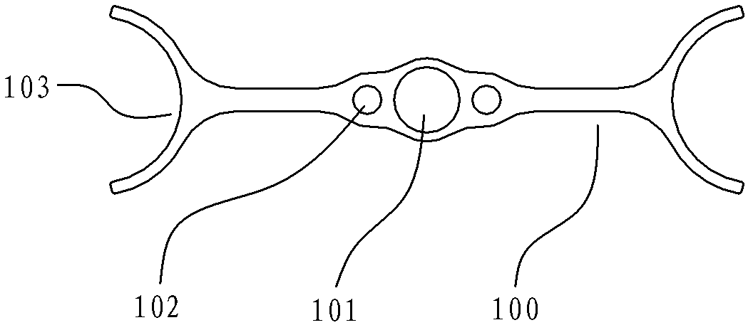
[0026] Such as figure 1 , figure 2 , the coupling flying rod 100 is a centrally symmetrical strip profile structure, the center of which is provided with a cylindrical fine-tuning coupling hole 101, and its two ends are provided with ring-shaped coupling discs 103, and in the fine-tuning coupling hole 101 Cylindrical screw fastening holes 102 are respectively provided on both sides.

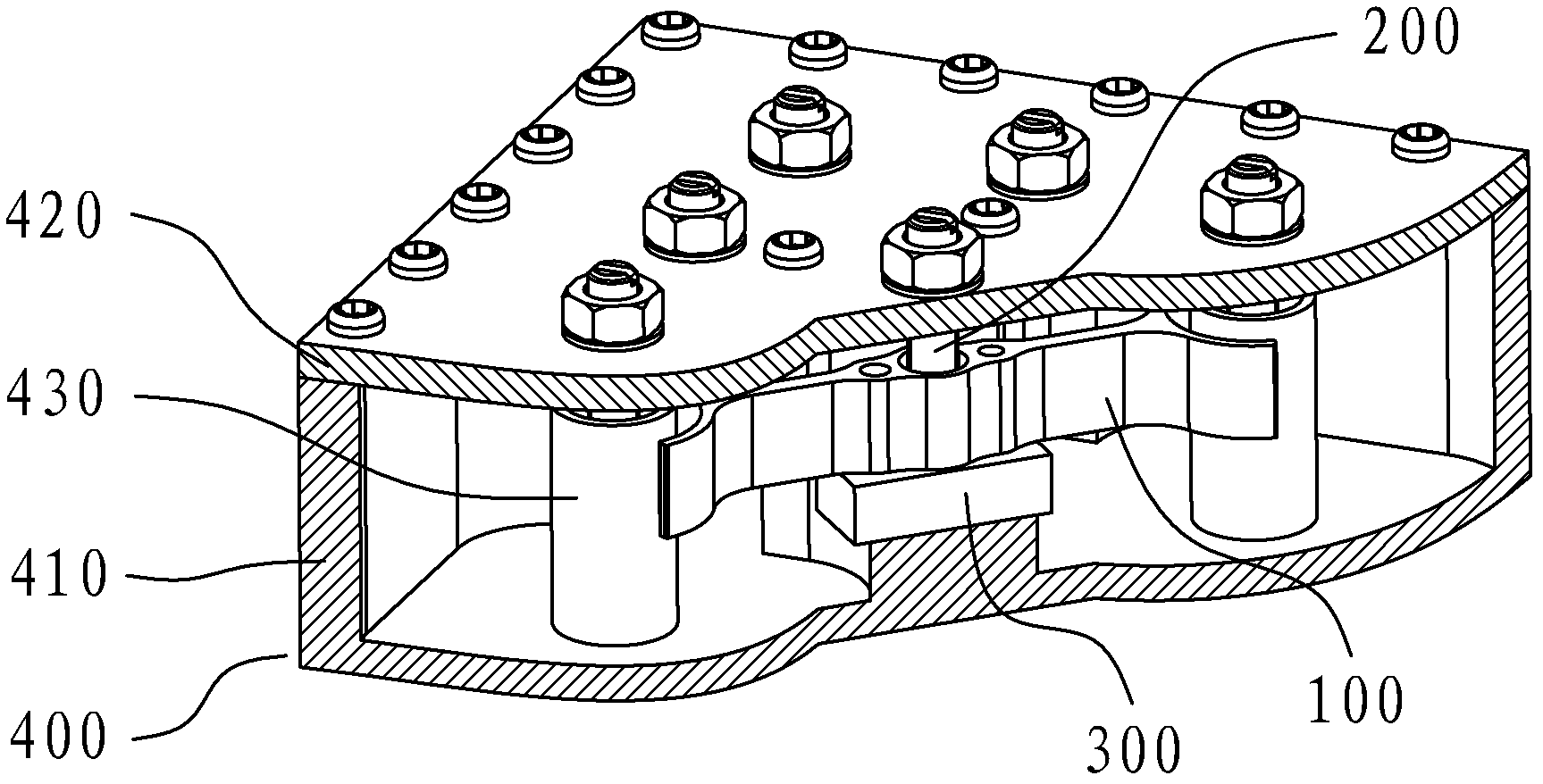
[0027] The fine-tuning coupling hole 101 cooperates with the fine-tuning coupling screw 200 to adjust the cross-coupling coefficient;

[0028] The screw fastening hole 102 is connected with the insulating support body 300 with the fastening screw 110;

[0029] The coupling plate 103 cooperates with the resonant column 430 to realize cross-coupling. The coupling surface of the coupling plate 103 is an annular surface parallel ...


PUM


Abstract

The invention discloses a capacitive cross coupling flying bar and a coaxial cavity resonator thereof, and relates to a cavity filter in the microwave communication field. The coupling flying bar is of a centre-symmetrical strip sectional material structure, wherein, the center of the coupling flying bar is equipped with a cylindrical fine-adjusting coupling hole; two ends of the coupling flying bar are respectively equipped with a coupling disk with an annular surface; and two sides of the fine-adjusting coupling hole are respectively equipped with a cylindrical screw fastening hole. The capacitive cross coupling flying bar has the advantages that the flying bar is a new sectional material structural form and is made by cutting a sectional material, wherein, the utilization ratio of the material is high and the machining process is simple, thus facilitating large-scale production; the coupling surfaces of the flying bar are the annular surfaces parallel to the cylindrical surfaces of resonant columns, and the coupling area is large and the distance is consistent, which can realize strong cross coupling by increasing the coupling area in the case of slightly long distance and ensure that a high-power signal can smoothly pass; and coupling coefficients are finely adjusted by a fine-adjusting coupling screw, which solves the problem of offset of the coupling coefficients caused by machining and assembly accuracy and ensures debugging consistency.

Description

technical field [0001] The invention relates to a cavity filter in the field of microwave communication, in particular to a capacitive cross-coupling fly rod between non-adjacent cavity resonators and a coaxial cavity resonator thereof. Background technique [0002] As a passive filter, the cavity filter does not require a power supply, is not prone to interference, and has a wide range of applications, and is widely used in the field of mobile communications. In the field of mobile communication, the cavity filter is used to separate and combine different frequencies, select the required signal frequency, and suppress the unnecessary signal frequency. [0003] At present, in multi-mode remote radio frequency units and multi-system integrated access systems, cavity filters are generally used to select signals at the antenna end or base station end. In order to meet the requirements of system operators for higher and higher network quality, the requirements for cavity filter...

Claims


Application Information

Patent Timeline
IPC IPC(8): H01P1/208H01P7/04H01P7/06
Inventor 吴卫华
Owner WUHAN HONGXIN TELECOMM TECH CO LTD
Learn More