Coaxial cable stripping machine

A technology of coaxial cable and wire stripping machine, which is applied in the direction of dismantling/armouring cable equipment, etc., can solve the problems of high cost, cumulative error cannot be eliminated, parallelism and unbalanced strength, etc., and achieve low manufacturing cost and wide application range Wide range and high production efficiency

Inactive Publication Date: 2012-02-22
昆山市张浦镇双威机械厂
View PDF4 Cites 5 Cited by
  • Summary
  • Abstract
  • Description
  • Claims
  • Application Information

AI Technical Summary

Problems solved by technology

[0003] At present, coaxial cable stripping machines are mainly used for stripping coaxial cables. There are two types of coaxial cable stripping machines on the market: fully automatic and semi-automatic. These two coaxial cable stripping machines have the following problems: 1. ) At present, most of the relatively stable automatic and semi-automatic wire stripping machines on the market are produced by companies such as Switzerland (Schleuniger), Japan and Taiwan (Chuangqun), and the prices are about 300,000 and 170,000 respectively. The cost of purchasing the machine is relatively high
2) The above-mentioned fully automatic and semi-automatic wire stripping machines can only peel one wire at a time. The stripping (both ends) of the fully automatic wire stripping machine is 400-500 wires/hour, and the efficiency of the semi-automatic wire stripping machine is about the same as that of the fully automatic machine. Half of the wire stripping machine, that is to say, it can only strip less than 250 strips, so the ef

Method used


Image

  • Coaxial cable stripping machine
  • Coaxial cable stripping machine
  • Coaxial cable stripping machine

Examples


Example Embodiment

[0022] The preferred embodiments of the present invention will be described in detail below in conjunction with the accompanying drawings.

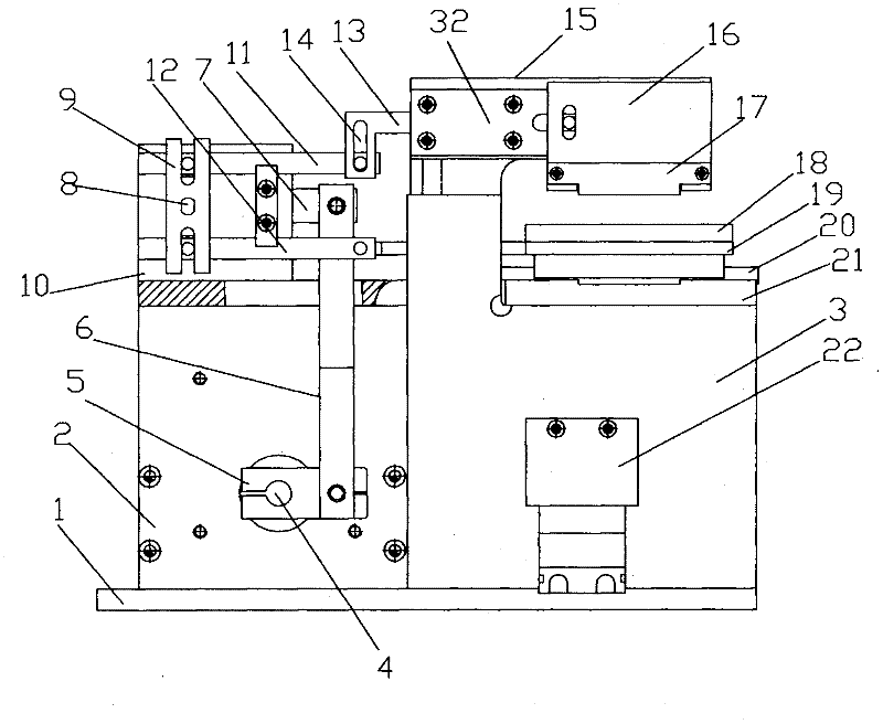
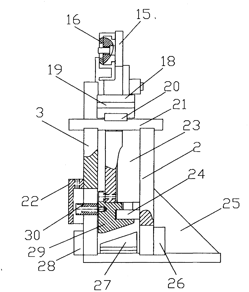
[0023] Such as figure 2 , 3 As shown, the coaxial cable stripping machine includes an upper sliding block 16 and a lower rubbing plate 18. The upper sliding block 16 is opposite to the lower rubbing plate 18, and a knife holder 17 is provided on the upper sliding block 16. Such as Figure 4 As shown, the knife holder 17 is provided with three blades 31, and the knife holder 17 is provided with three T-shaped grooves. The three blades 31 are T-shaped and respectively clamped in the three T-shaped grooves. The number of blades 31 can be stripped according to the The type of wire is changed, and the number of blades is generally between 1-4. The upper sliding block 16 is also provided with a T-shaped groove, and the tool holder 17 is clamped in the T-shaped groove of the upper sliding block 16 to prevent the blade from falling off. The height...


PUM


Abstract

The invention discloses a coaxial cable stripping machine, which comprises an upper sliding block and a lower twisting plate, wherein the upper sliding block is opposite to the lower twisting plate; a tool rest is arranged on the upper sliding block; blades are arranged on the tool rest; the upper sliding block and the lower twisting plate are connected with a swinging mechanism; the swinging mechanism can drive the upper sliding block and the lower twisting plate to move in opposite direction at a constant speed; the upper sliding block is also connected with a longitudinal driving mechanism; and the longitudinal driving mechanism can drive the upper sliding block to move up and down. The coaxial cable stripping machine is simple in structure, low in manufacturing cost and quite high in production efficiency; because the upper sliding block and the lower twisting plate move in the opposite direction at the constant speed and then twist each other, wire materials of the whole row can be subjected to skin cut-off operation at the same time; and because the upper sliding block can move up and down, a distance between the upper sliding block and the lower twisting plate can be adjusted. Therefore, the coaxial cable stripping machine can be applied to coaxial cables with various kinds of diameters, is high in universality and wide in application range, and can effectively meet requirements on production.

Description

technical field [0001] The invention relates to a wire stripping machine, in particular to a wire stripping machine for stripping coaxial cables. Background technique [0002] Antennas are mainly used in radio transmission and reception, such as mobile phones, computers, cordless phones, cars and wireless remote control equipment, so they are used in a large amount. The coaxial cable is a main part in the antenna, and its structure is as follows figure 1 As shown, it includes outer covering layer 1, metal braiding layer 2, insulating layer 3 and conductor 4, etc. When the coaxial cable is used, it is necessary to peel off the skins of the outer covering layer 1, the metal braiding layer 2, and the insulating layer 3 respectively. [0003] At present, coaxial cable stripping machines are mainly used for stripping coaxial cables. There are two types of coaxial cable stripping machines on the market: fully automatic and semi-automatic. These two coaxial cable stripping machin...

Claims


Application Information

Patent Timeline
IPC IPC(8): H02G1/12
Inventor 刘玉俊
Owner 昆山市张浦镇双威机械厂
Why Eureka
Try Eureka