

Single switching tube high-grain converter based on coupling inductance voltage-multiplying unit
A technology of coupled inductor and single switch, which is applied in the direction of electrical components, adjusting electric variables, output power conversion devices, etc., can solve the problems of complex circuit structure and small voltage gain, so as to improve the voltage gain and suppress the turn-off voltage spike Effect
- Summary
- Abstract
- Description
- Claims
- Application Information
AI Technical Summary
Problems solved by technology
Method used
Image

Examples
Embodiment 1
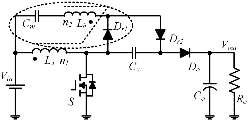
[0016] Refer to attached figure 1 , 2 , a single-switch high-gain converter based on a coupled inductor voltage doubler unit, which includes a coupled inductor La and Lb with primary and secondary windings, a voltage doubler capacitor Cm, a switched capacitor Cc, and an output capacitor C0, Two freewheeling diodes Dr1, Dr2, an output diode D0, and a switch tube S; the first end of the primary winding La of the coupling inductor is connected to the positive pole of the input power supply Vin and the first end of the voltage multiplier capacitor Cm, and the coupling The second end of the primary winding La of the inductor is connected to the drain of the switching tube S, the anode of the first freewheeling diode Dr1 and the first end of the switching capacitor Cc; the first end of the secondary winding Lb of the coupled inductor is connected to The second end of the voltage multiplying capacitor Cm is connected, and the second end of the secondary winding Lb of the coupled ind...
Embodiment 2
[0027] see image 3 The difference between this implementation and Embodiment 1 is that the first end of the voltage doubler capacitor is connected to the negative pole of the input voltage source, the source pole of the switch tube, one end of the output capacitor and one end of the output load, and the rest of the structure is the same as All functions are the same.
Embodiment 3
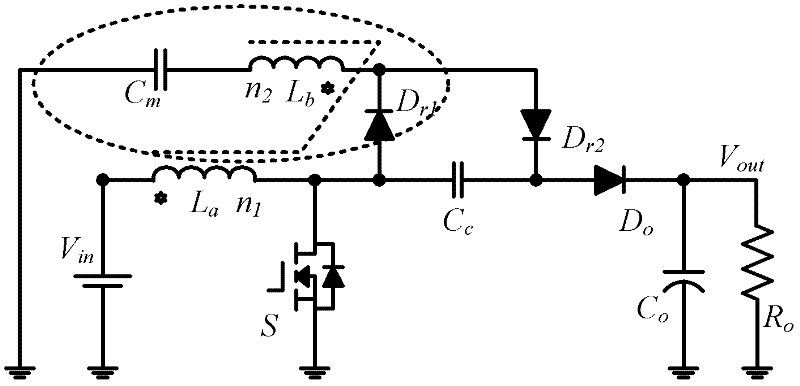
[0029] see Figure 4 The difference between this implementation and Embodiment 1 is that the first terminal of the voltage doubler capacitor is connected to the cathode of the output diode, one terminal of the output capacitor and one terminal of the output load, and the rest of the structures and functions are the same.
PUM
 Abstract
Description
Claims
Application Information