Pulse width modulation (PWM) control circuit and control method for peak current mode inverter

A peak current mode and control circuit technology, applied in the direction of converting AC power input to DC power output, electrical components, output power conversion devices, etc., can solve transformer transformer corrosion, large total harmonic distortion, and positive half cycle of output current and negative half-cycle asymmetry to achieve the effect of improving quality, eliminating DC components, and reducing THD value

Inactive Publication Date: 2012-02-29
XI AN JIAOTONG UNIV
View PDF4 Cites 12 Cited by
  • Summary
  • Abstract
  • Description
  • Claims
  • Application Information

AI Technical Summary

Problems solved by technology

However, this control method has a prominent shortcoming, that is, the positive and negative half cycles of the output current are asymmetrical, contain a large DC component, and its total harmonic distortion (THD) value is relatively large.
The DC component in the output current will have adverse effects on power grid equipment, such as causing saturation of transformers or transformers, corrosion of substation grounding grids, etc., which has also become a bottleneck restricting its further development and application

Method used


Image

  • Pulse width modulation (PWM) control circuit and control method for peak current mode inverter
  • Pulse width modulation (PWM) control circuit and control method for peak current mode inverter
  • Pulse width modulation (PWM) control circuit and control method for peak current mode inverter

Examples


Embodiment Construction

[0023] The present invention is described in further detail below in conjunction with accompanying drawing:

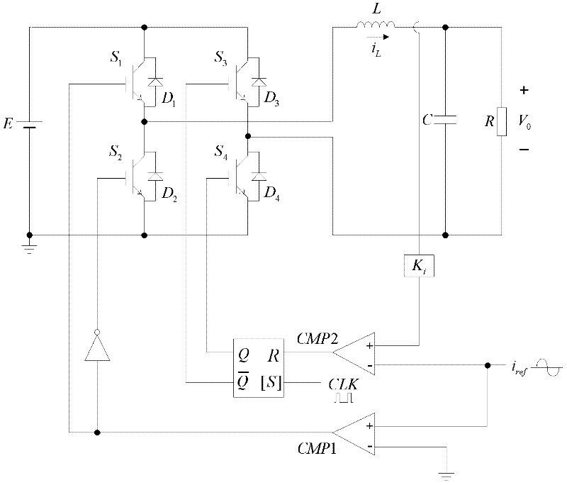
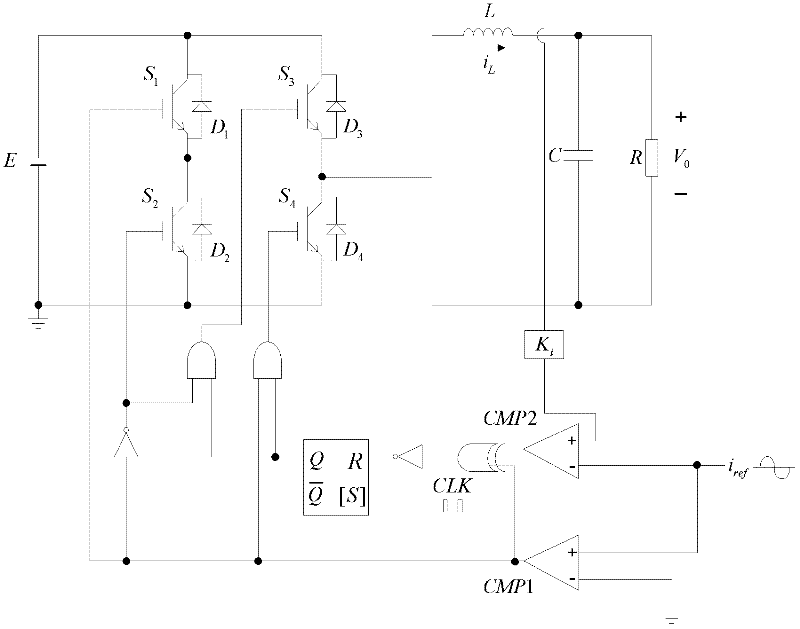
[0024] attached figure 2 Shown is the circuit diagram of the peak current mode inverter PWM control designed by the present invention. Among them, the switch tube S of the direction arm 1 , S 2 Still use the reference current and the comparison value of the zero-crossing comparator for control. In order to realize the positive half-cycle and negative half-cycle symmetry of the output current, the comparison value of the reference current and the output current and the output of the zero-crossing comparator are connected to the R input port of the RS flip-flop through an appropriate gate circuit combination; and then the RS flip-flop The Q output and the output of the zero-crossing comparator are combined through an appropriate gate circuit to control the switch tube S 3 , S 4 .

[0025] The design of the gate circuit is carried out according to the following ste...


PUM


Abstract

The invention discloses a pulse width modulation (PWM) control circuit and a PWM control method for a peak current mode inverter. The control method comprises the following steps of: listing input and output values of a comparator and an RS trigger and a truth table corresponding to control signals required by four switching tubes according to the working principle of the peak current mode inverter; determining logical relationships between the control signals of the four switching tubes and the output values of the comparator and the RS trigger; and adding a corresponding gate circuit according to the logical relationships to finish PWM control in a peak current mode over the switching tubes. By the method, the symmetry of positive and negative half cycles of output current is realized, a direct current component is eliminated, a total harmonic distortion (THD) value of the output current is decreased, the waveform quality of the output current is improved and protection over power grid equipment is realized.

Description

Technical field: [0001] The invention belongs to the field of power electronic systems, and relates to a PWM control method for a peak current mode inverter, in particular to a PWM control method for a peak current mode inverter. Background technique: [0002] According to the type of feedback loop, the pulse width modulation (PWM) method of the inverter includes two control modes of voltage and current. The current control mode can be divided into peak current mode, average current mode and so on. The peak current mode not only has the advantages of fast dynamic response and good regulation performance, but also can realize the current limitation of the output current, so as to avoid the phenomenon of overcurrent damage to the power device. Therefore, the peak current mode has been widely used in practice. [0003] attached figure 1 Shown is the PWM control circuit diagram of a conventional peak current mode inverter. The switching tube S of the H-bridge inverter 1 , S...

Claims


Application Information

Patent Timeline
Patent Type & Authority Applications(China)
IPC IPC(8): H02M7/5387H02M1/14
Inventor 张浩关为民石琳马西奎
Owner XI AN JIAOTONG UNIV
Why Eureka
Try Eureka