Engine base punching die

An engine and punching technology, applied in the field of punching dies, can solve the problems of poor surface quality of holes on the bottom sheet, low processing efficiency, pollution of the surrounding environment, etc., to ensure production safety, reasonable die structure, and good force effect. Effect

Inactive Publication Date: 2012-03-07
CHONGQING BEIBEI DISTRICT FENGHUO MACHINERY MFG
View PDF3 Cites 15 Cited by
  • Summary
  • Abstract
  • Description
  • Claims
  • Application Information

AI Technical Summary

Problems solved by technology

[0002] The engine base is used to connect and fix the engine of the motor vehicle to the vehicle body and absorb the vibration and noise emitted by the engine to a certain extent. It is connected with the engine and the vehicle body by bolts, and the connection is parallel and symmetrical. For the thin plate structure, the processing of the connecting holes is generally processed by drilling or punching. The connecting holes processed by the drilling process can get better surface quality after grinding, but the processing efficiency Low, a large amount of iron powder and iron filings will be produced during the drilling process, which will pollute the surrounding environment and pose a threat to the operator's personal health, and the grinding of the hole requires more human resources and higher production costs; At present, the punching process of the engine base is generally to place the movable die inside the workpiece, and then punch the punch from top to bottom to form the hole. The disadvantage is that the surface quality of the hole on the bottom sheet is poor, and it needs to be processed Grinding treatment, high production cost, and each time the die needs to be manually placed inside the workpiece, it is impossible to accurately position the die relative to the punch, and processing accidents are prone to occur

Method used


Image

  • Engine base punching die
  • Engine base punching die
  • Engine base punching die

Examples


Embodiment Construction

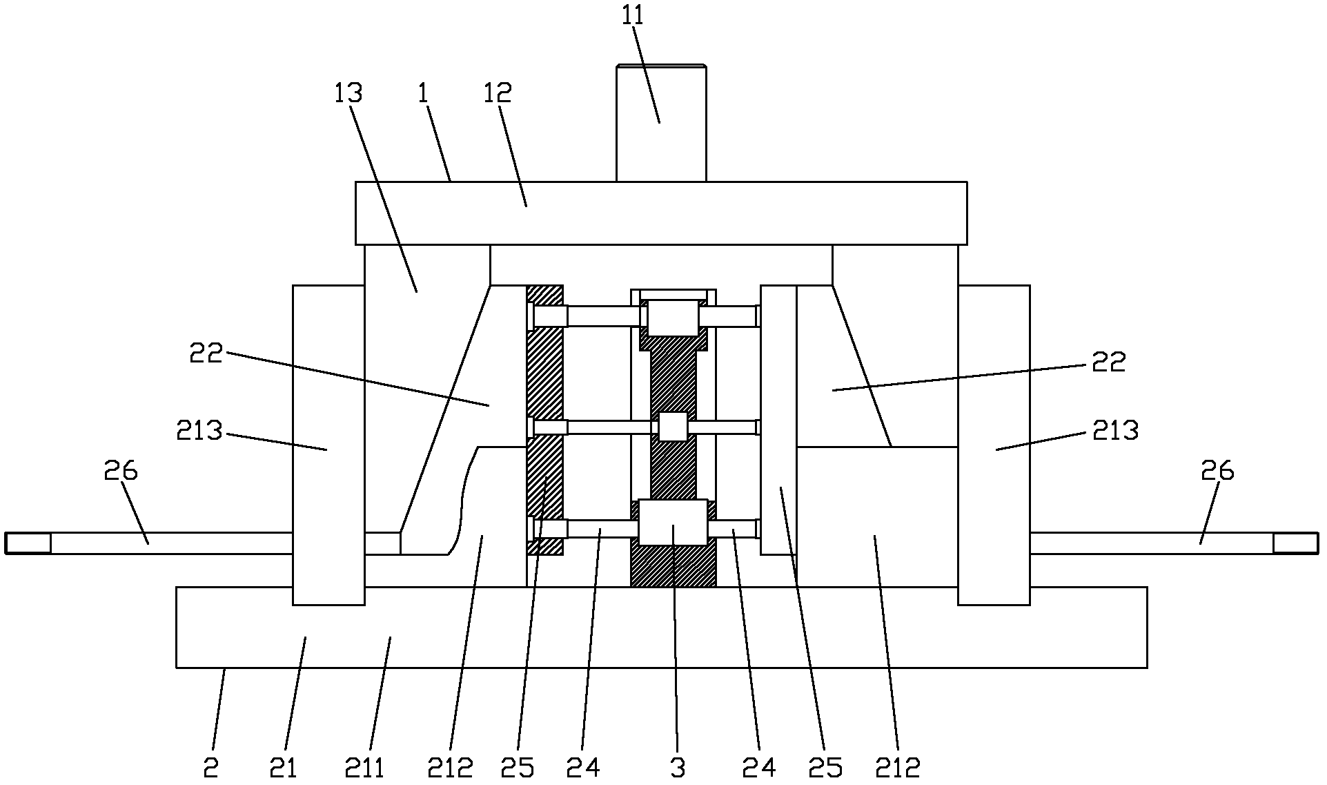
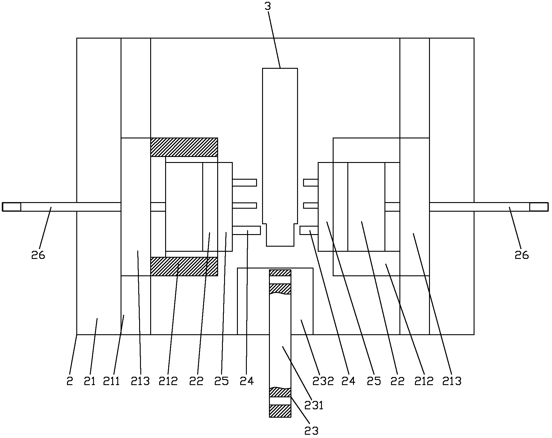
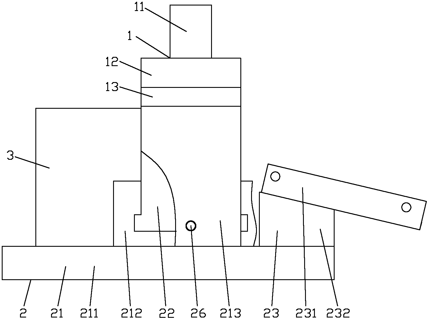
[0019] figure 1 It is the front view of the present invention, figure 2 It is a top view of the present invention, image 3 It is the left view of the present invention, as shown in the figure: the engine base punching die of this embodiment includes an upper die 1, a lower die 2 and a die 3, and the upper die 1 includes a fixed plate 12 connected to a punch handle 11 And the wedge block 13 that is fixed on the lower surface of the fixed plate 12, on the wedge block 13, an inclined surface is provided on one side corresponding to the direction of movement of the punch for punching; The base 21 of the horizontal slide rail, the slide block 22 slidably connected to the slide rail, and the workpiece positioning device 23 fixed on the base, the slide block 22 is provided with a On the inclined surface matched with the inclined surface on the wedge block, a punch 24 is fixedly arranged on one side of the slider 22 corresponding to the moving direction of punching processing alon...


PUM


Abstract

The invention discloses an engine base punching die which comprises an upper die, a lower die and a female die, wherein the upper die comprises a fixing plate connected with a die shank and wedge-shaped blocks fixed on the lower surface of the fixing plate, and inclined planes are formed on the two wedge-shaped blocks; the lower die comprises a base provided with a horizontal slide rail, slide blocks in sliding connection with the slide rail and a workpiece positioning device fixed on the base, inclined planes corresponding to the inclined planes on the wedge-shaped blocks are formed on the slide blocks, a punching head is fixedly arranged at one side of the punching motion direction of each slide block, and the workpiece positioning device is used for positioning a workpiece in a bolt fastening mode; and the female die is positioned between the two slide blocks and is fixed on the base, and a guide hole is formed on the female die in the position corresponding to the punching head. The hole processed by using the engine base punching die disclosed by the invention has better surface quality, no need of grinding and high production efficiency; the female die can not generate collision with the motion of the punching head; the structure of the die is reasonable; each component has good stress effect; and the production safety can be effectively ensured.

Description

technical field [0001] The invention relates to a punching die, in particular to a punching die which can process holes with better surface quality on two symmetrical thin plates at the junction of an engine base. Background technique [0002] The engine base is used to connect and fix the engine of the motor vehicle to the vehicle body and absorb the vibration and noise emitted by the engine to a certain extent. It is connected with the engine and the vehicle body by bolts, and the connection is parallel and symmetrical. For the thin plate structure, the processing of the connecting holes is generally processed by drilling or punching. The connecting holes processed by the drilling process can get better surface quality after grinding, but the processing efficiency Low, a large amount of iron powder and iron filings will be produced during the drilling process, which will pollute the surrounding environment and pose a threat to the operator's personal health, and the grindi...

Claims


Application Information

Patent Timeline
Patent Type & Authority Applications(China)
IPC IPC(8): B21D28/26B21D28/34B21D37/10
Inventor 艾刚涂定国
Owner CHONGQING BEIBEI DISTRICT FENGHUO MACHINERY MFG
Why Eureka
Try Eureka