Cutter driving device in gear processing machine

A driving device and processing machine technology, applied in the direction of gear tooth manufacturing device, driving device, metal processing machinery parts, etc., can solve the problems of reducing the rotation speed of the main shaft, poor mechanical stability, and incompatibility of the main shaft structure, and achieves improved processing. Accuracy and efficiency, reliable high-speed rotation, safe and reliable work

Inactive Publication Date: 2012-03-07
NINGBO YINZHOU TAISHENG NUMERICAL CONTROL EQUIP
View PDF7 Cites 1 Cited by
  • Summary
  • Abstract
  • Description
  • Claims
  • Application Information

AI Technical Summary

Problems solved by technology

[0002] Among mechanical products, gear products account for the majority. Generally, the tool is fixed by the tool driving device in the gear processing machine, and then the tool is reciprocated on the axis of the workpiece by rotating the tool and rotating the workpiece to mesh with each other. The workpiece is formed into the required gear shape. Due to the structural design problems of the existing tool driving device, the main shaft and the bearing mainly adopt the sliding fit method, so that when the main shaft drives the tool to rotate, the speed can only reach 70 m / s. Minute action, which limits the range of use of the processing machine, and the use of sliding fit increases the gap, the friction coefficient becomes larger, and the internal structure of the main shaft is not tightly matched, resulting in large gap jumps and poor mechanical stability. It is necessary to reduce the rotation speed of the main shaft, making it difficult to ensure the machining accuracy and efficiency of the gear

Method used


Image

  • Cutter driving device in gear processing machine
  • Cutter driving device in gear processing machine

Examples


Embodiment Construction

[0017] The following are specific embodiments of the present invention and in conjunction with the accompanying drawings, the technical solutions of the present invention are further described, but the present invention is not limited to these embodiments.

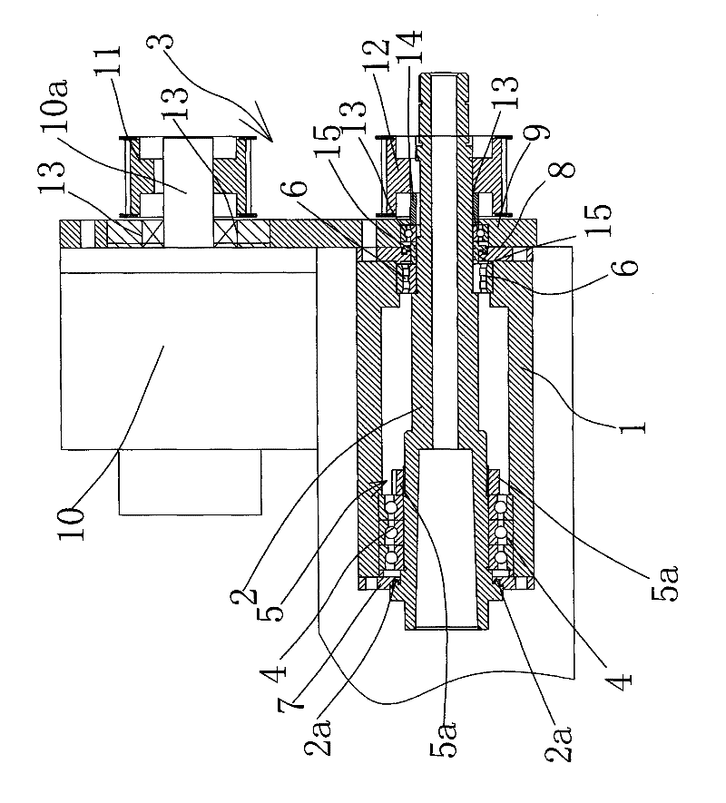
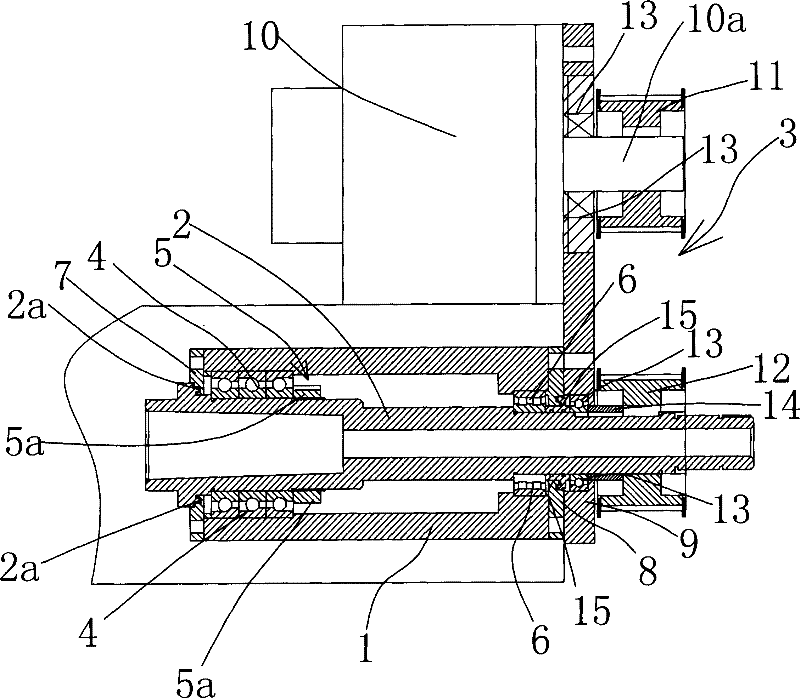
[0018] In the figure, tool holder 1; main shaft 2; step surface 2a; driving mechanism 3; angular contact bearing 4; adjustment member 5; lock nut 5a; cylindrical roller bearing 6; left bearing end cover 7; right bearing end cover 8; Fixed plate 9; motor 10; motor shaft 10a; upper pulley 11; lower pulley 12; centripetal ball bearing 13; adjustment sleeve 14;

[0019] Such as figure 1 As shown, the tool driving device in this gear processing machine includes a tool seat 1, a main shaft 2 and a driving mechanism 3, the main shaft 2 is arranged in the tool seat 1, and a left bearing end is arranged between the front end of the tool seat 1 and the main shaft 2 The cover 7 is provided with a right bearing end cover 8 between th...


PUM


Abstract

The invention belongs to the technical field of machinery and provides a cutter driving device in a gear processing machine. The cutter driving device comprises a cutter holder, a main shaft and a driving mechanism, wherein the main shaft is arranged in the cutter holder, the driving mechanism drives the main shaft to do rotational motion, multiple groups of angular contact bearings are arranged between the front end part in the cutter holder and the main shaft, the angular contact bearings and the main shaft are in angular contact, the edges of the angular contact bearings are provided with adjusting parts used for adjusting gaps among the angular contact bearings along the axial direction of the main shaft, and a cylindrical roller bearing is arranged between the rear end part in the cutter holder and the main shaft. The cutter driving device provided by the invention has the advantages that two types of bearings are combined and arranged so that the main shaft jumps in a small range, a rolling fit manner is adopted to ensure the reliable and high-speed operation of the main shaft, and a problem caused by temperature can be well controlled by adjusting elasticity of the gaps among the angular contact bearings by locking nuts, thus the main shaft is ensured to operate stably, safely and reliably, and processing accuracy and efficiency of a gear are improved.

Description

technical field [0001] The invention belongs to the technical field of machinery and relates to a gear processing machine, in particular to a tool driving device in the gear processing machine. Background technique [0002] Among mechanical products, gear products account for the majority. Generally, the tool is fixed by the tool driving device in the gear processing machine, and then the tool is reciprocated on the axis of the workpiece by rotating the tool and rotating the workpiece to mesh with each other. The workpiece is formed into the required gear shape. Due to the structural design problems of the existing tool driving device, the main shaft and the bearing mainly adopt the sliding fit method, so that when the main shaft drives the tool to rotate, the speed can only reach 70 m / s. Minute action, which limits the range of use of the processing machine, and the use of sliding fit increases the gap, the friction coefficient becomes larger, and the internal structure of ...

Claims


Application Information

Patent Timeline
Patent Type & Authority Applications(China)
IPC IPC(8): B23Q5/04B23B19/02B23F23/00
Inventor 吕琦王伟雄
Owner NINGBO YINZHOU TAISHENG NUMERICAL CONTROL EQUIP
Why Eureka
Try Eureka