Continuous automatic line conveying equipment unit capable of synchronously and medially clamping

A technology of conveying equipment and automatic lines, which is applied to conveyor objects, conveyor control devices, transportation and packaging, etc., can solve the problems of high manufacturing cost, low transmission efficiency, poor operation stability, etc., and achieve the effect of solving pause and rigid impact.

Inactive Publication Date: 2012-03-07
张荣
View PDF4 Cites 21 Cited by
  • Summary
  • Abstract
  • Description
  • Claims
  • Application Information

AI Technical Summary

Problems solved by technology

The current automated assembly line has the disadvantages of poor operation stability, low transmission efficiency, and high manufacturing cost.

Method used


Image

  • Continuous automatic line conveying equipment unit capable of synchronously and medially clamping
  • Continuous automatic line conveying equipment unit capable of synchronously and medially clamping
  • Continuous automatic line conveying equipment unit capable of synchronously and medially clamping

Examples


Embodiment 1

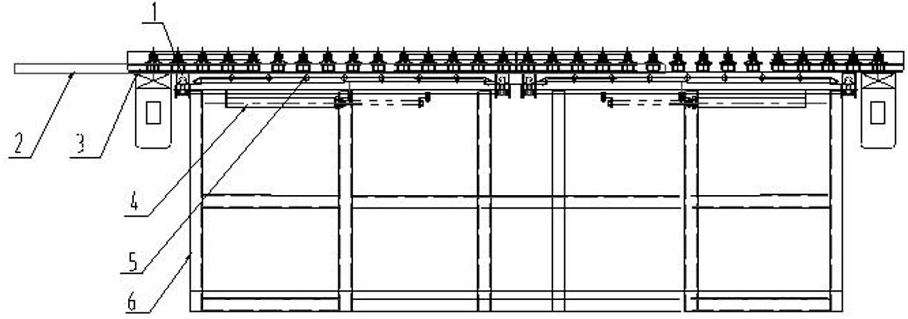
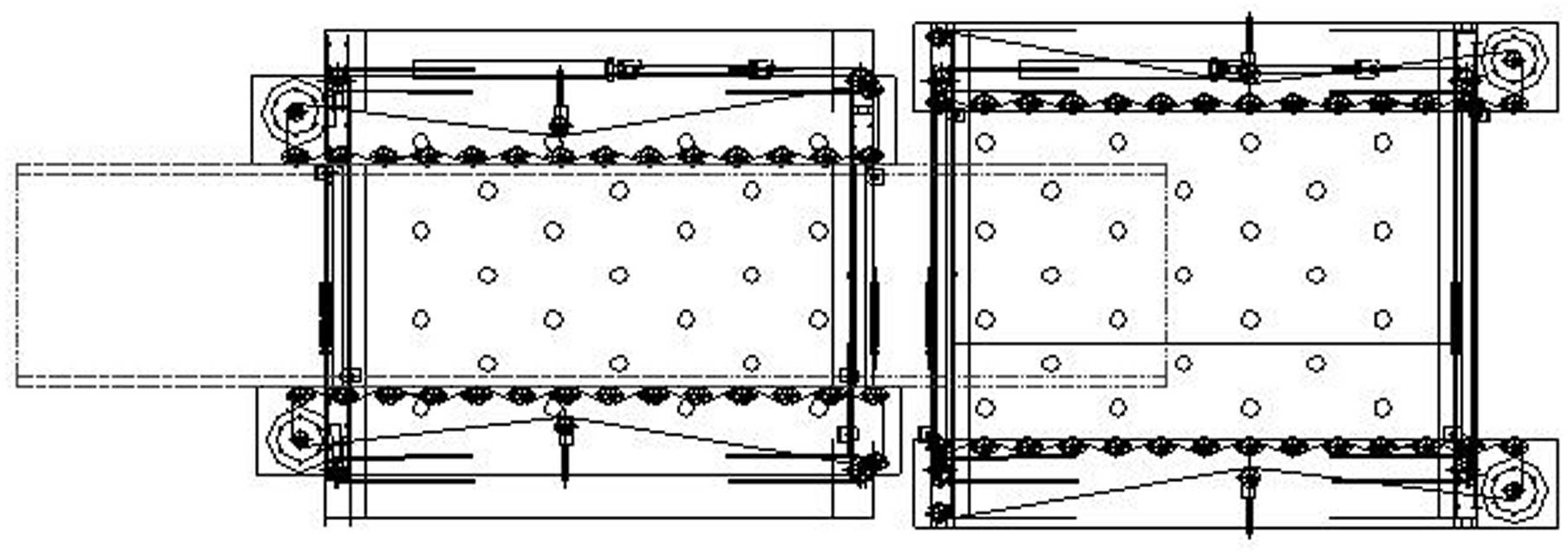
[0023] Example 1 as Figure 1 to Figure 9 shown. Wherein, the overall structure of embodiment 1 is as follows figure 1 , figure 2 shown. The synchronous centering clamping continuous transmission equipment unit of the present invention is composed of a slider assembly 1 , a product diagram 2 , a linear transmission mechanism 3 , a synchronous centering clamping mechanism 4 , a working surface 5 , and a fixed bracket 6 . Work surface 5 is the work surface with universal ball. The invention is suitable for processing the following materials: stainless steel, color-coated plates and oil-free cold-rolled steel plates, sheet metal parts with a plate thickness less than or equal to 2.0 mm. The invention provides the function of automatically synchronously centering the product and continuously conveying the workpiece at high speed, and performs the start and stop function according to the process requirements, and cooperates with the process to automatically complete the necess...

Embodiment 2

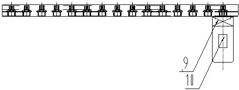
[0029] The center clamping structure of embodiment 2 is as Figure 10 to Figure 12 As shown, it is a centered clamping structure of 3 sets of sliders. The difference from Embodiment 1 is that Embodiment 1 is a transmission device with one group of power and one synchronous centering clamping mechanism, and Embodiment 2 is a transmission device with multiple groups of power and multiple synchronous centering clamping mechanisms. 2 steel wire wheels and 2 steel wires have been added in embodiment 2, but structure and mode of operation are the same as Figure 7 to Figure 9 Same as in the implementation shown.


PUM


Abstract

The invention discloses a continuous automatic line conveying equipment unit capable of synchronously and medially clamping, belonging to the technical field of continuous automatic line conveying equipment. The continuous automatic line conveying equipment mainly solves the problems of poor operation stability and low conveying efficiency of the traditional automatic line conveying unit. The continuous automatic line conveying equipment unit mainly comprises a synchronous and medial clamping mechanism and a linear conveying mechanism, wherein the synchronous and medial clamping mechanism comprises a power part, a transmission part and an execution part; and the execution part comprises two groups or more than two groups of sliding block assemblies and brackets. The continuous automatic line conveying equipment unit is characterized in that one set of power part and one set of transmission part simultaneously control two groups or more than two groups of execution parts to make the movement of synchronously and medially clamping; the linear conveying mechanism is installed on one side or two sides of a synchronous and medial clamping mechanism; a conveyor belt is surrounded between rubber coating idler wheel groups in S shape; and continuous conveying power is provided while the workpiece is synchronously and medially clamped. The continuous automatic line conveying equipment unit has the characteristics of good stability and high conveying efficiency and is mainly used for continuously conveying the workpieces of a synchronous and medial clamping box type structure on the automatic line.

Description

technical field [0001] The invention belongs to the technical field of continuous conveying equipment between processes in an automated assembly line, and can realize single-point or multi-point synchronous centering clamping for independent conveying equipment units while providing linear transmission power, and is more suitable for pipelines in which multiple conveying equipment units are used in series. It is used on the automatic assembly line, which can automatically and synchronously clamp the box-type structural workpiece in the center, and at the same time provide the transmission equipment for continuous transmission of linear power. On the automatic assembly line, it can automatically assist each station equipment to complete the corresponding section punching and sizing through PLC programming. , Reinforcing rib fixing, spot welding, welding, riveting, assembly and other process contents, it has the advantages of high synchronization centering precision, high transmi...

Claims


Application Information

Patent Timeline
Patent Type & Authority Applications(China)
IPC IPC(8): B65G47/90B65G43/08
CPCY02P70/10
Inventor 张荣
Owner 张荣
Why Eureka
Try Eureka