Electrically charged isolator

A technology of isolators and cones, applied in the direction of electrical components, switchgear, etc.

Inactive Publication Date: 2012-03-07
LUOHE POWER SUPPLY OF HENAN ELECTRIC POWER CORP
View PDF4 Cites 0 Cited by
  • Summary
  • Abstract
  • Description
  • Claims
  • Application Information

AI Technical Summary

Problems solved by technology

[0004] In order to solve the technical problems existing in the existing high-voltage drop fuse devices, the present invention hereby provides a live isolator, which can realize that w

Method used


Image

  • Electrically charged isolator
  • Electrically charged isolator
  • Electrically charged isolator

Examples


Embodiment Construction

[0015] Introduce embodiments of the present invention below in conjunction with accompanying drawing:

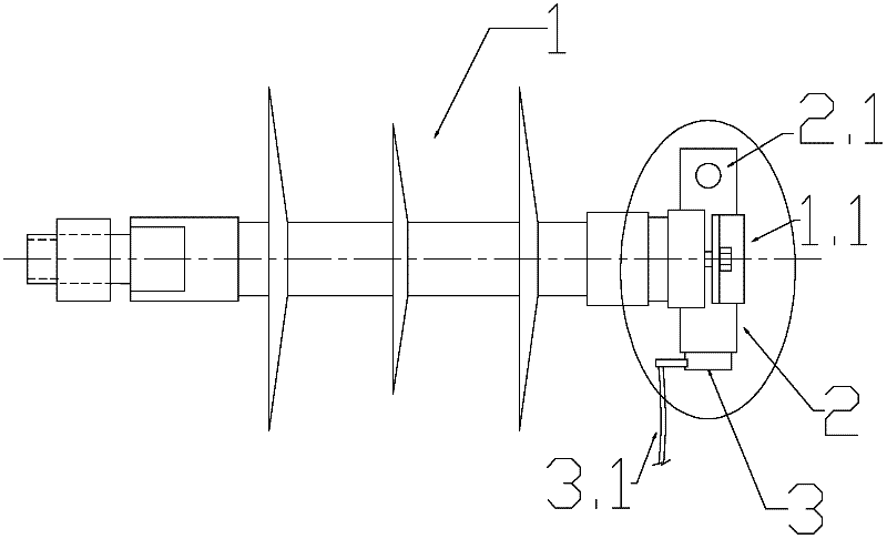
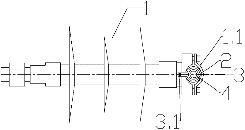
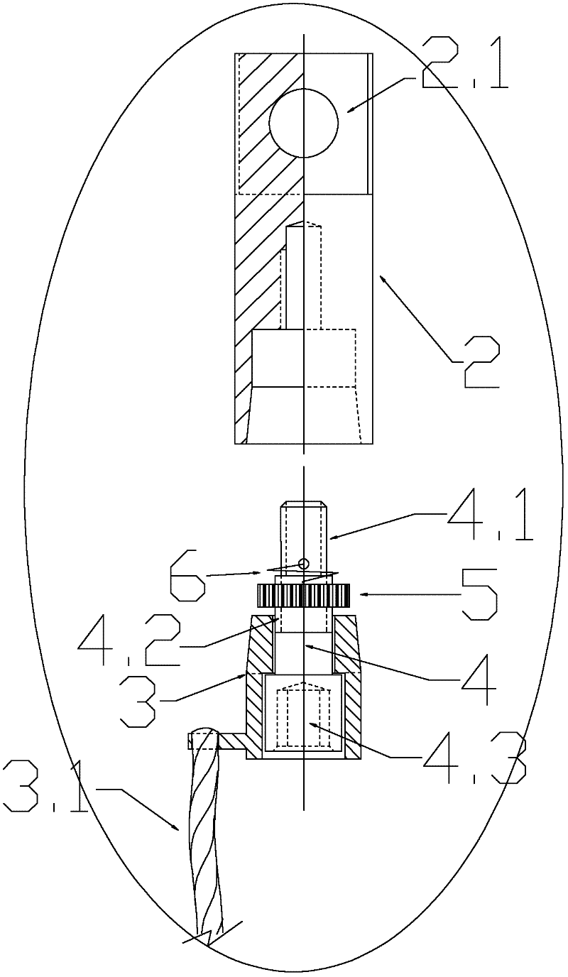
[0016] Such as figure 1 , 2 , 3, the live isolator is mainly composed of an insulator 1, a conical sleeve body 2, a conical core body 3, a double thread bolt 4, a push nut 5 and a return spring 6.

[0017] The tail end of the insulator 1 is the installation end, which is used for overall fixing on the cross arm of the pole. The head end of the insulator 1 is fixedly connected to the cone sleeve 2. The axis of the cone sleeve 2 is perpendicular to the axis of the insulator 1. The cone sleeve The body 2 is pressed and fixed by the clamping plate 1.1 of the insulator 1 with fasteners to form the fixed part of the live isolator; the central screw hole of the tapered sleeve body 2 is connected to the coarse thread 4.1 of the double-threaded bolt 4, and the double-threaded bolt 4 Go through the central through hole of the conical surface core body 3, and a push nut 5 is installe...


PUM


Abstract

The invention discloses an electrically charged isolator. The isolator comprises: an insulator, a conical surface sleeve body, a conical surface core body, a double threaded bolt, a pushing nut and a restoring spring. The conical surface sleeve body is arranged at a position where one end of the insulator is vertical to an axis of the insulator. The conical surface sleeve body is connected with a coarse thread of the double threaded bolt. The double threaded bolt passes through a center through hole of the conical surface core body. The pushing nut is installed on a fine thread portion. A resetting device, which can prevent the pushing nut from loosening, is arranged between the pushing nut and the double threaded bolt. The conical surface sleeve body cooperates with a conical surface of the conical surface core body so as to form electric contact. A wiring point, which is used to connect a power-distribution-network high-voltage line, is arranged on a terminal portion of the conical surface sleeve body. A connected tail line, which is used to connect a high-voltage dropping fuse, is arranged on a rail of the conical surface core body. The electrically charged isolator has a simple structure. And a volume of the electrically charged isolator is smaller than the volume of an isolation disconnecting link. Reliability, economy, an electrical property, compatibility of environment and equipment and the like of the electrically charged isolator surpass that of the isolation disconnecting link. However, the electrically charged isolator can not cut off a load current. The electrically charged isolator can be widely used in the domestic distribution network. Power failure and reparation of the distribution network caused by damage of the high-voltage dropping fuse can be eliminated.

Description

technical field [0001] The invention relates to an isolator in a power distribution system in the electric power industry, in particular to a live isolator. Background technique [0002] In my country's urban and rural power distribution systems, high-voltage drop fuses are widely used as protection components and switching components of public distribution transformers connected under public lines. The working conditions are relatively harsh and the failure rate is high. Once a fault occurs, the power supply enterprise must deal with maintenance: the city-level power supply unit can dispatch live work vehicles for maintenance. A public line was shut down for maintenance. Generally, a plurality of public transformers are connected to one public line, which enlarges the negative impact of a damaged high-voltage drop fuse on society and enterprises. [0003] There is a wiring method for this, that is, install a set of isolation knife switch above the high-voltage drop fuse o...

Claims


Application Information

Patent Timeline
IPC IPC(8): H02B3/00
Inventor 叶淼叶冰
Owner LUOHE POWER SUPPLY OF HENAN ELECTRIC POWER CORP
Why Eureka
Try Eureka